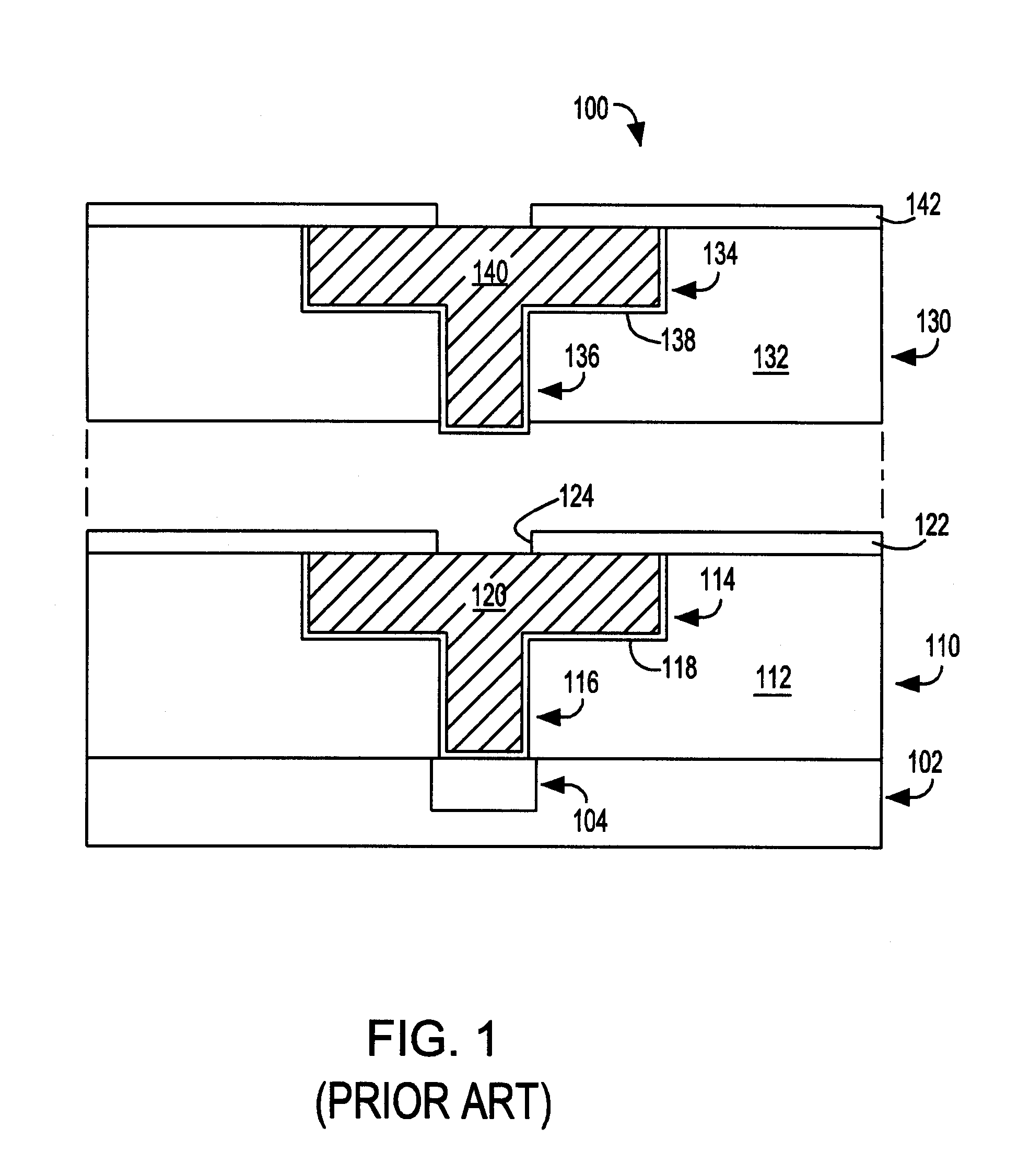
De-fluorination after via etch to preserve passivation

a technology of passivation and fluorination, which is applied in the direction of semiconductor/solid-state device manufacturing, basic electric elements, electric devices, etc., can solve the problems of increasing the number of circuit elements, increasing the difficulty of efficient routing of these signals across the device, and materials which perform best as etch stop layers typically do not perform best as passivation layers, so as to improve device/beol interconnect reliability and functionality, increase passivation layer retention, and reduce the effect of ild modification

Inactive Publication Date: 2006-05-11
GOOGLE LLC
View PDF9 Cites 17 Cited by
  • Summary
  • Abstract
  • Description
  • Claims
  • Application Information

AI Technical Summary

Benefits of technology

[0048] In keeping with these and other objects of the present invention, there is provided an interconnect structure built in a dense OSG low-k dielectric film in which a low power density/high pressure oxygen-based plasma process is utilized to enable increased passivation layer retention (selectivity) during via level damascene processing and, thus, improve device/BEOL interconnect reliability and functionality.
[0049] As mentioned above, during the etching of the via (136), a relatively thick (typically >10 nm) layer of polymeric material is usually formed which ought to be removed without perturbing the underlying passivation (e.g., NBLoK; SiCNH) layer (122). This polymeric layer is normally removed during the subsequent oxygen-based ashing step (oxygen based chemistries are preferred for ashing dense OSG-based materials versus nitrogen and/or hydrogen-based chemistries because of the reduced ILD modification effect of the former compared with the latter) but may also induce etching of the underlying NBLoK film by the following mechanism. Since the chamber walls and wafer surface (in addition to the via structures) are well laden with fluorine-based polymer accrued during the via etch processing steps; the ash process can serve to liberate chamber wall and wafer fluorine such that subsequent to the removal of the atop polymeric layer within the ...

Problems solved by technology

Efficient routing of these signals across the device can become more difficult as the complexity and number of circuit elements are increased.
Often the passivation layer must also function as an etch stop layer during subsequent processing, however materials which perform best as etch stop layers typically do not perform best as passivation layers.
Silicon oxynitride, SiON, is usually preferred as a etch stop layer but is less desirable as a passivation layer because of delamination which can occur between copper and silicon oxynitride.
Silicon nitride, SiN, avoids the delamination problem, and is a preferred passivation material, but is less desirable as an etch stop layer.
As a result, it is very difficult to prepare a CVD film with a k v...

Method used


Image

  • De-fluorination after via etch to preserve passivation

Examples


Embodiment Construction

[0061] In the description that follows, numerous details are set forth in order to provide a thorough understanding of the present invention. It will be appreciated by those skilled in the art that variations of these specific details are possible while still achieving the results of the present invention. However, well-known processing steps may not be described in detail in order to avoid unnecessarily obfuscating the description of the present invention.

[0062] Materials (e.g., silicon dioxide) may be referred to by their formal and / or common names, as well as by their chemical formula. Regarding chemical formulas, numbers may be presented in normal font rather than as subscripts. For example, silicon dioxide may be referred to simply as “oxide”, chemical formula SiO2. For example, silicon nitride (stoichiometrically Si3N4, often abbreviated as “SiN”) may be referred to simply as “nitride”.

[0063] In the description that follows, exemplary dimensions may be presented for an illus...


PUM


Abstract

Novel interconnect structures possessing a dense OSG material for 90 nm and beyond BEOL technologies in which a low power density oxygen-based de-fluorination plasma process is utilized to increase NBLoK selectivity are presented. These BEOL interconnect structures are capable of delivering enhanced reliability and performance due to the reduced risk of Cu exposure and hence electromigration and stress migration related failures. The oxygen based de-fluorination process is such that the plasma conditions employed {low power density (<0.3 Wcm−2); relatively high pressure (>100 mT); negligible ion current to wafer surface (applied source frequency only)} facilitate a physical expulsion of residual fluorine present on the chamber walls, wafer surface, and within the via structure; thus, minimizing the extent of NBLoK etching that can occur subsequent to removing polymeric byproducts of via etching.

Description

BACKGROUND OF THE INVENTION [0001] The present invention relates to semiconductor device fabrication, more particularly to techniques for via level processing of organosilicate glass (OSG) based interlevel dielectric (ILD) materials and, more particularly, to techniques for removing polymer residue associated with via processing, particularly in a damascene process. [0002] An integrated circuit (IC) device (also referred to as a semiconductor chip) can contain millions of transistors and other circuit elements that are fabricated on a single silicon crystal substrate (wafer). For the IC device to be functional, a complex network of signal paths will normally be routed to connect the circuit elements distributed on the surface of the device. Efficient routing of these signals across the device can become more difficult as the complexity and number of circuit elements are increased. Thus, the formation of multi-level or multi-layered interconnection schemes such as, for example, dual ...

Claims


Application Information

Patent Timeline
IPC IPC(8): H01L21/44
CPCH01L21/02063H01L21/76807
Inventor FULLER, NICHOLASDALTON, TIMOTHY J.
Owner GOOGLE LLC
Why Eureka
Try Eureka