Electron beam pumped laser light source for projection television

a laser light source and laser technology, applied in the direction of cathode-ray/electron-beam tube electrical connection, semiconductor laser, etc., can solve the problems of difficult and expensive to optically capture the emitted light, difficult and expensive modulation with an slm, and inability to meet the requirements of consumer projection televisions, etc., to achieve the effect of improving the overall performance and efficiency of the laser, high thermal conductivity, and easy to mak

Inactive Publication Date: 2006-07-27
PRINCIPIA LIGHTWORKS
View PDF2 Cites 24 Cited by
  • Summary
  • Abstract
  • Description
  • Claims
  • Application Information

AI Technical Summary

Benefits of technology

[0018] Advantageously, most opaque substrates with high thermal conductivity are also electrically conductive to some extent. Therefore such a substrate can be connected to a suitable ground or other voltage appropriate to the particular design, and then the substrate can effectively provide a path for the electrons that would otherwise increase in number in the semiconductor's valence band due to the electron beam pumping. In summary, because the substrate is not required to be transparent, it can easily be made of an electrically conductive material such as metal that provides a low resistance path to ground. Even a substrate made of GaAs is more electrically conductive than transparent materials such as sapphire or glass. Therefore, using the electrically conductive substrate connected to ground, excess charge would not build up within the semiconductor, thereby improving overall performance and efficiency of the laser.
[0019] A method is disclosed of making the laser faceplate that takes advantage of the cost benefits and greater efficiency of the epitaxial growth processes. This method includes growing a highly reflective layer on an substrate (e.g., a DBR), growing a semiconductor gain layer on the highly reflective layer, forming a partially reflective layer on the gain layer, thereby providing an optical cavity between the highly reflective layer and the partially reflective layer; and connecting the substrate to a heat removal system. The step of forming a partially reflective layer may include growing a distributed Bragg reflector on the semiconductor layer. The step of growing the gain layer may include defining a MQW structure in the semiconductor gain layer.

Problems solved by technology

Alternative light sources such as LEDs or laser diodes are either impractical or non-existent for consumer projection televisions because they require too much power for consumer use and are too expensive.
For example, the large light emitting surfaces of multiple LEDs make it difficult and expensive to optically capture the emitted light and difficult and expensive to modulate it with an SLM.

Method used


Image

  • Electron beam pumped laser light source for projection television
  • Electron beam pumped laser light source for projection television
  • Electron beam pumped laser light source for projection television

Examples


Embodiment Construction

[0033] This invention is described in the following description with reference to the Figures, in which like numbers represent the same or similar elements.

Glossary of Terms and Acronyms

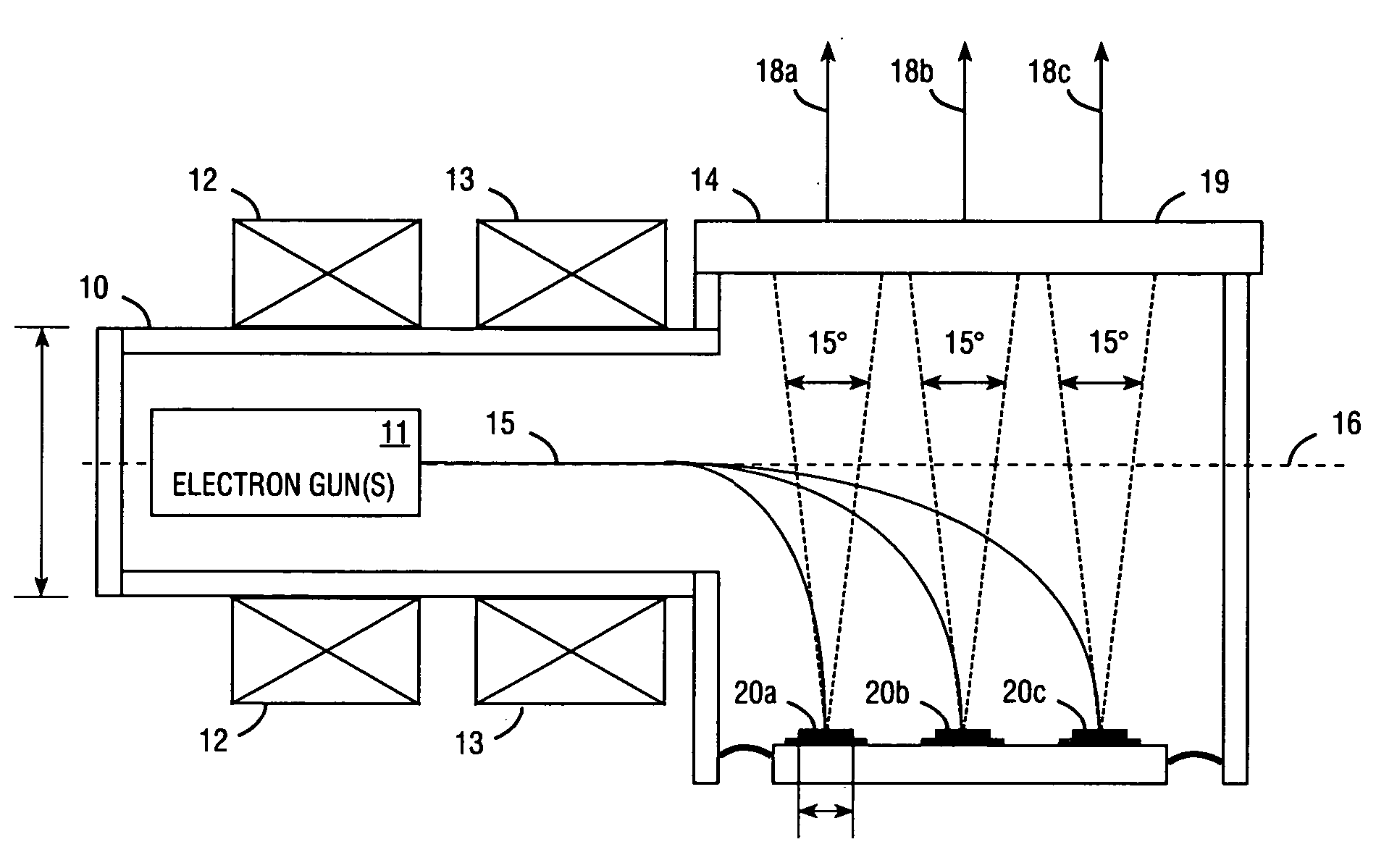
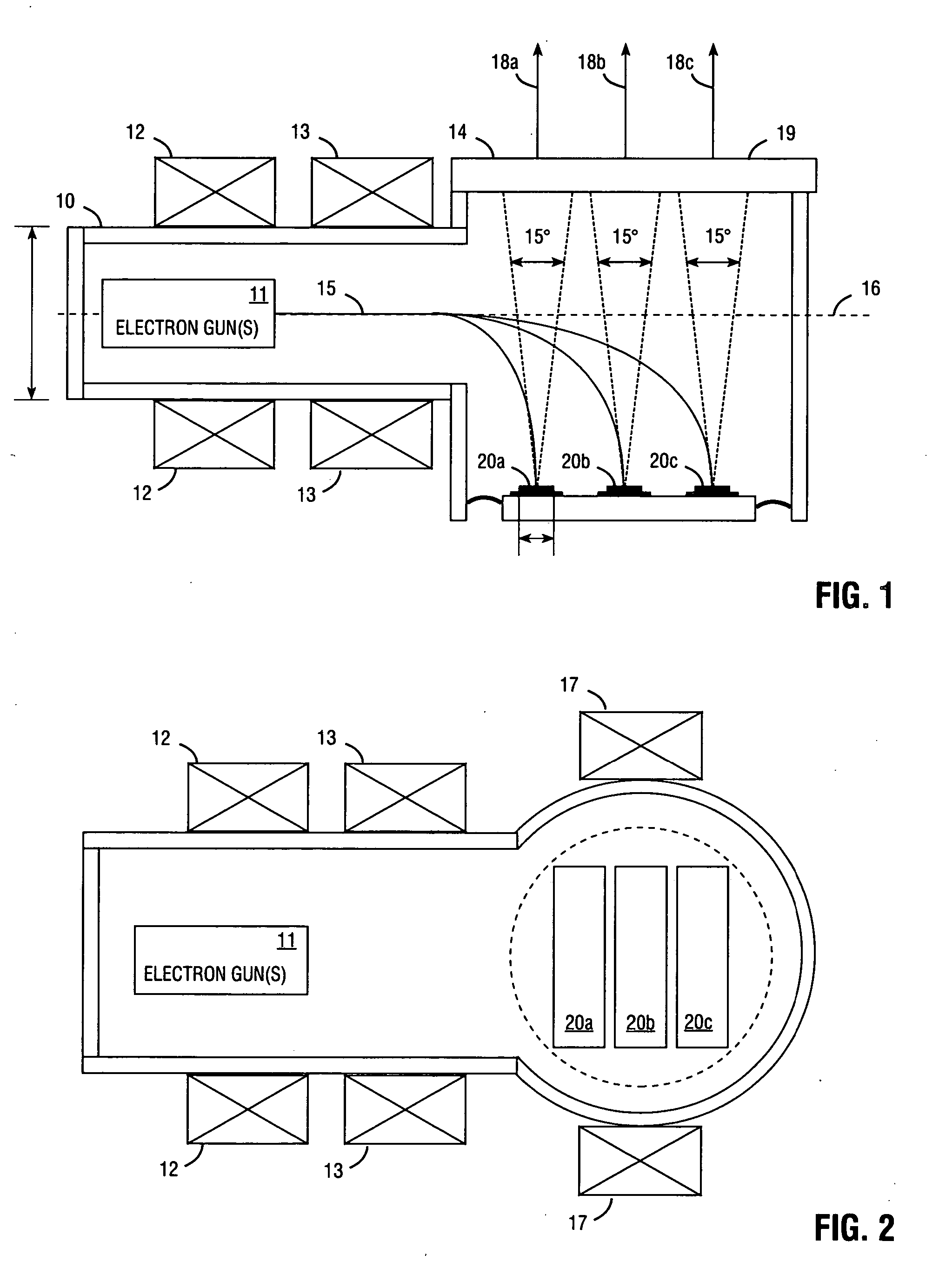
[0034] The following terms and acronyms are used throughout the detailed description: [0035] eVCSEL electron beam-pumped vertical cavity surface emitting laser [0036] Laser-CRT (LCRT) a cathode ray tube with a laser faceplate [0037] CRT cathode ray tube [0038] e-beam electron beam emitted from an electron gun in a CRT [0039] electron beam spot the area within which the e-beam energy is concentrated on the laser faceplate [0040] electron beam the axis of electron beam emission from the electron gun [0041] emission axis [0042] orientation angle the angle of the faceplate with respect to the electron beam emission axis [0043] bending angle the angle through which the e-beam is bent before striking the faceplate [0044] CTE Coefficient of Thermal Expansion [0045] MQW multiple quantum well [0046] low-di...


PUM


Abstract

An electron beam pumped laser including a surface-emitting laser faceplate oriented at a non-perpendicular angle. Embodiments are described in which a bending coil bends the electron beam, or in which the faceplate is situated in the direct path of the e-beam emission but with a non-zero orientation angle. The faceplate may include a substantially opaque substrate, and an opaque heat-removing structure may be attached to the substrate to provide high heat transfer, thereby allowing high electron-beam pumping intensity and providing more light emission from a smaller package. In some embodiments the partially reflective mirror comprises a metal layer that has a plurality of openings. Multiple laser faceplates (e.g., red, green, and blue) may be placed in the same tube, to provide a continuous light source for projection television. The substrate may be connected to ground to provide an exit path for electrons from the laser gain layer.

Description

BACKGROUND OF THE INVENTION [0001] 1. Field of the Invention [0002] The present invention generally relates to electron beam pumped lasers, and particularly to electron beam pumped lasers such as those that provide a light source for projection television. [0003] 2. Description of Related Art [0004] Projection televisions for consumer applications utilize a white light source such as a xenon or halogen lamp, dichroic filters to separate the red, green and blue light components, and a spatial light modulator (SLM) to modulate the red, green, and blue light. The modulated light is then projected through appropriate optics to generate an image. A number of SLM technologies may be used, such as liquid crystal panels, digital micro-mirrors, and grating light valves, for example. Alternative light sources such as LEDs or laser diodes are either impractical or non-existent for consumer projection televisions because they require too much power for consumer use and are too expensive. For ex...

Claims


Application Information

Patent Timeline
Patent Type & Authority Applications(United States)
IPC IPC(8): H01J29/86H01J29/92
CPCB82Y20/00H01J29/89H01J2229/8928H01S3/0604H01S3/0627H01S3/09H01S3/0906H01S3/169H01S5/04H01S5/183H01S5/34H01S5/3412
Inventor TIBERI, MICHAEL D.KOZLOVSKY, VLADIMIR I.
Owner PRINCIPIA LIGHTWORKS
Why Eureka
Try Eureka