
Continuous flow chamber device for separation, concentration, and/or purification of cells

a flow chamber and cell technology, applied in the field of cell separation methods and apparatuses, can solve the problems of reducing the overall yield of cells, increasing the cost of the process, and reducing the yield of cells, so as to achieve fewer steps, reduce the cost of the process, and improve the effect of cell separation efficiency

Inactive Publication Date: 2006-08-17
UNIVERSITY OF ROCHESTER
View PDF5 Cites 52 Cited by
  • Summary
  • Abstract
  • Description
  • Claims
  • Application Information

AI Technical Summary

Benefits of technology

[0011] The advantage of the present invention is that it requires fewer steps and subjects the cells to a more physiologically relevant environment, as opposed to the artificial and harsh environment utilized by current other methods of cell separation. The present invention does not use expensive purified antibodies, and is cheaper, faster, and more efficient. The present device will enable physicians to treat cancers, immunodeficiency, hematological, and, potentially, cardiac diseases with greater efficacy.
[0012] The device of the present invention contains a surface for cell rolling, wherein the surface has been coated with a substance that chemically or physically adheres to the type of cell being separated, concentrated, or purified (the desired cells). In use, a mixture of cells is allowed to flow along the surface. Because the desired cells roll at a different velocity than the other cells in the mixture due to the adhesion between the desired cells and the coated surface, it can be separated, concentrated, or purified from the other cells.
[0013] The adhesion molecule may be specific for a region of a protein, such as a prion, a capsid protein of a virus or some other viral protein, and so on. A target specific adhesion molecule may be a protein, peptide, antibody, antibody fragment, a fusion protein, synthetic molecule, an organic molecule (e.g., a small molecule), or the like. In general, an adhesion molecule and its biological target refer to a ligand / anti-ligand pair. Accordingly, these molecules should be viewed as a complementary / anti-complementary set of molecules that demonstrate specific binding, generally of relatively high affinity. Cell surface moiety-ligand pairs include, but are not limited to, T-cell antigen receptor (TCR) and anti-CD3 mono or polyclonal antibody, TCR and major histocompatibility complex (MHC)+antigen, TCR and super antigens (for example, staphylococcal enterotoxin B (SEB), toxic shock syndrome toxin (TSST), etc.), B-cell antigen receptor (BCR) and anti-immunoglobulin, BCR and LPS, BCR and specific antigens (univalent or polyvalent), NK receptor and anti-NK receptor antibodies, FAS (CD95) receptor and FAS ligand, FAS receptor and anti-FAS antibodies, CD54 and anti-CD54 antibodies, CD2 and anti-CD2 antibodies, CD2 and LFA-3 (lymphocyte function related antigen-3), cytokine receptors and their respective cytokines, cytokine receptors and anti-cytokine receptor antibodies, TNF-R (tumor necrosis factor-receptor) family members and antibodies directed against them, TNF-R family members and their respective ligands, adhesion / homing receptors and their ligands, adhesion / homing receptors and antibodies against them, oocyte or fertilized oocyte receptors and their ligands, oocyte or fertilized oocyte receptors and antibodies against them, receptors on the endometrial lining of uterus and their ligands, hormone receptors and their respective hormone, hormone receptors and antibodies directed against them, and others. Other examples may be found by referring to U.S. Pat. No. 6,265,229; U.S. Pat. No. 6,306,575 and WO 9937751, which are incorporated herein by reference. Most preferably, the adhesion molecules are antibodies, selectins, cadherins, integrins, mucin-like family, immunoglobin superfamily or fragments thereof. The adhesion between the selected cells and the adhesion molecule is preferably transient, such that when exposed to the shear rate of a flow field, preferably in the range of 50-1000 s−1, the cells do not bind to tightly to the adhesion molecule, but rather roll along the coated surface.
[0014] Adhesion molecules can be coated on the surface by directly physisorbing (absorbing) the molecules on the surface. Alternatively, the adhesion molecules can be covalently attached to the surface by reacting —COOH with —NH2 groups on silanated glass surfaces. Another method for attachment of adhesion molecules is to first absorb or attach avidin protein (including variants such as “Neutravidin” or “Superavidin”) to the surface, and then reacting this avidin-coated surface with adhesion molecules containing a biotin group. Electrostatic charge or hydrophobic interactions can be used to attach adhesion molecules on the surface. Other methods of attaching molecules to surfaces are apparent to those skilled in the art, and depend on the type of surface and adhesive molecule involved.
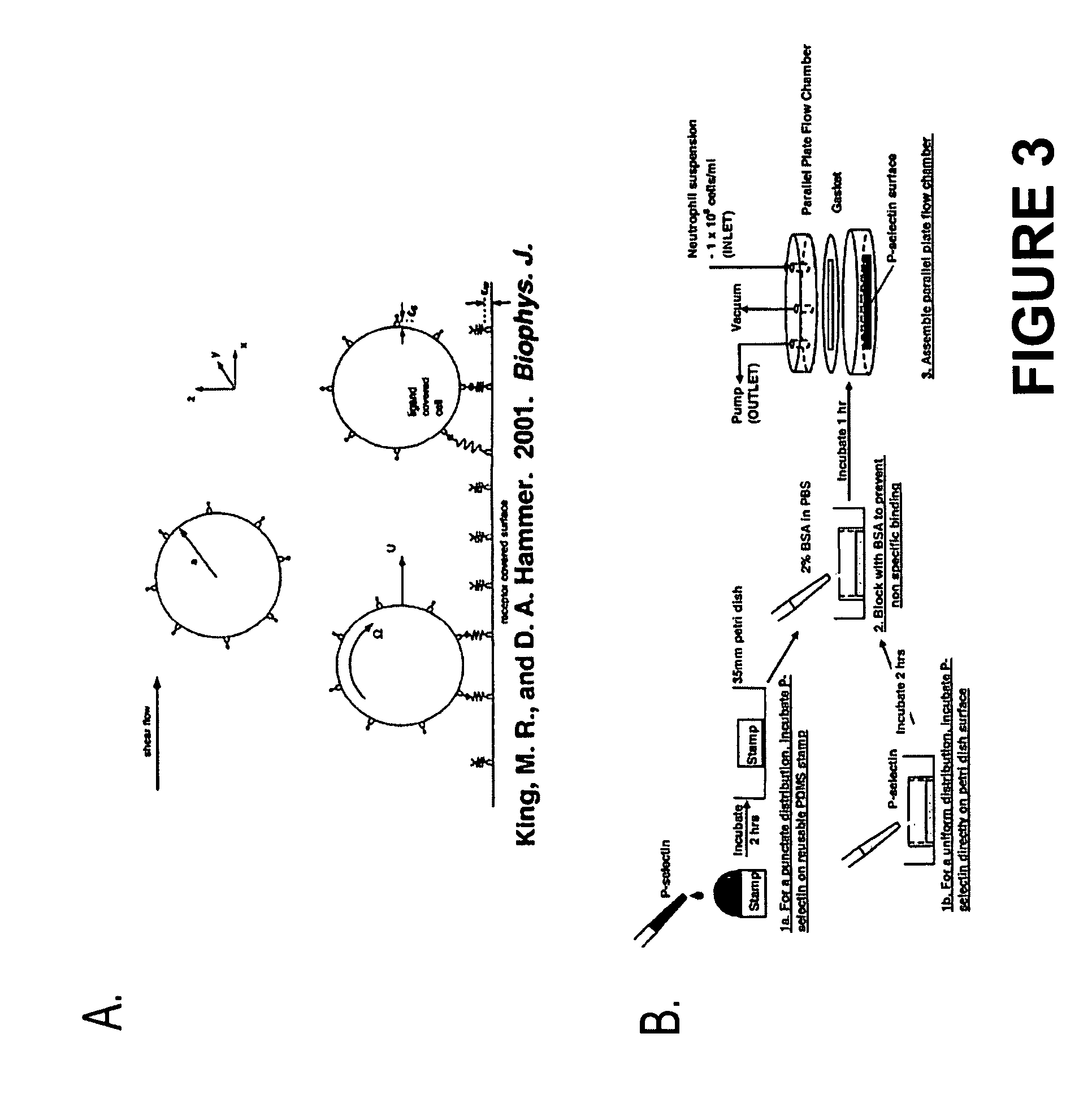
[0015] In a preferred embodiment, the adhesive molecule is micropatterned on the rolling surface to improve separation, concentration, and / or purification efficiency. The pattern is preferably a punctated disctribution of the adhesive molecule as described by King (Fractals, 12(2):235-241, 2004), which is incorporated herein by reference. Here, punctate refers to adhesion molecule concentrated in small discrete spots instead of as a uniform coating, which can be in any variety of patterns Punctate micropatterns or other micropatterns can be produced through microcontact printing. This is where a microscale stamp is first incubated upside-down with the adhesion molecule solution as a drop resting on the micropatterned (face-up) surface. Then the drop is aspirated off, the microstamp surface quickly blown dry with nitrogen gas, and then the microstamp surface quickly placed face down on the substrate. A small 10-20 g / cm2 weight can be added to the stamp to facilitate transfer of the adhesion molecule onto the substrate. Then the substrate is removed and a micropattern of adhesion molecule remains on the surface.
[0016]FIG. 4 compares adhesion of flowing cells on either micropatterned or uniform adhesive surfaces. In FIG. 4A, the average rolling velocity of cells on a micropattern is significantly lower than on a uniform surface of equal average density, and the micropattern is even slower than a uniform surface with a much higher average density. In FIG. 4B, it is shown the rolling flux (number of adhesively rolling cells) is high on the micropattern, is high on the uniform surface with a much higher average density than the micropattern, and is low on the uniform surface with average density matched to the micropattern. Thus, micropatterns of adhesive molecule can be used to capture specific flowing cells much more effectively and efficiently than uniform adhesive surfaces. FIG. 4C shows as picture of a punctate micropattern of adhesive molecule, 3×3 micron squares of P-selectin micropatterned on tissue culture polystyrene.

Problems solved by technology

Such affinity column separations require several distinct steps including incubation of the cells with the antibody, elution of the cells, cell collection, and release of the conjugated antibody, with each step reducing the overall yield of cells and increasing the cost of the process.
In order to obtain a sufficient amount of a biological target, a large amount of sample, such as peripheral blood, must be obtained from a donor at one time, or samples must be withdrawn multiple times from a donor and then subjected to one or more lengthy, expensive, and often low-yield separation procedures to obtain a useful preparation of the biological target.
Taken together, these problems place significant burdens on donors, separation methods, technicians, clinicians, and patients.
These burdens significantly add to the time and costs required to isolate the desired cells.
Hematopoietic stem and precursor cells (HSPC) are able to restore the host immune response through bone marrow transplantation, yet the demand for these cells far exceeds the available supply.

Method used


Image

  • Continuous flow chamber device for separation, concentration, and/or purification of cells
  • Continuous flow chamber device for separation, concentration, and/or purification of cells
  • Continuous flow chamber device for separation, concentration, and/or purification of cells

Examples


example 1

[0063] In order to establish protocol without sacrificing precious HSPCs, we utilized a model system where CD34+ KG1a cells represented the HSPCs and CD34− HL60 cells represented the CD34− ABM cells. The KG1a / HL60 model was used to determine an optimum P-selectin concentration for subsequent HSPC experiments. We initially found that KG1a and HL60 cells rolled at very similar velocities at all P-selectin concentrations tested so, based on the data from Eniola et al. (2003), we co-immobilized anti-CD34 antibody together with the P-selectin and found that, at 0.5 μg / ml P-selectin and 40 μg / ml anti-CD34, there was a significant difference between the rolling velocities of the two cells (FIG. 6A). This more closely represented previous findings that HSPCs tend to roll slower than CD34− cells on selecting, which was further confirmed by our own HSPC / CD34− ABM cells experiments using 0.5 μg / ml P-selectin (FIG. 6B). The presence of the antibody had little effect on the rolling velocity of t...

example 2

[0064] Cell retention as a function of time was also determined for both cell models at a shear stress of 3 dyn / cm2 for 10 minutes. Cells were initially loaded over the entire surface and allowed to settle for 40 s for KG1a / HL60 cells, and 2 minutes for ABM cells, based on the Stokes settling velocity of the cells of interest. We found that KG1a Cells had a higher accumulation than HL60 cells on the P-selectin / antibody surface and similarly, there was higher retention of HSPCs than Cd34− ABM cells on the P-selectin surface (FIG. 7).

[0065] We were able to use this data to predict and confirm with experiments that there would be significant enrichment of KG1a cells for KG1a / HL60 cell mixtures ranging from 10-50% KG1a cells. Predictions using physiologic ABM concentrations of 1-5% HSPC showed more modest improvements and were not confirmed experimentally (FIG. 8).

[0066] We extended the prediction to determine the length of time for optimum enrichment, i.e., the time for purity and re...

example 3

[0067] As mentioned before, we established conditions for determining the effectiveness of our system based on recommendations from Johnsen et al (1999)—Cell purity >80-90%, Cell retention >50% and optimum separation within 30 minutes. It was evident that our current system needed significant improvements to achieve these preliminary goals, so we investigated whether our cell loading system was optimized for this type of separation. Instead of loading the entire surface, only a small portion (<10%) of the surface would be used for the initial cell loading step so that the device could make use of the natural tendency of the cells to separate based on rolling velocity (FIG. 10).

[0068] We used an exponentially modified Gaussian (EMG) distribution to describe the velocity distribution of cells at 3 dyn / cm2 (FIG. 11). The peak to peak resolution for HL60 / KG1a cells and HSPC / CD34− ABM cells was about 0.4, corresponding to about 40% cross contamination. Coupled with the cell retention da...


PUM


Abstract

The present invention relates to methods and apparatuses for cell separation. In particular, the invention relates to separation of a particular cell type from a mixture of different cell types based on the differential rolling property of the particular cell type on a substrate coated with molecules that exhibits adhesive property with the particular cell type. This technology is adaptable for use in implantable shunts and devices for cell trafficking or tumor neutralization.

Description

[0001] This application claims priority of U.S. Provisional Patent Application Nos. 60 / 696,797, filed Jul. 7, 2005; 60 / 682,843, filed May 20, 2005; and 60 / 645,012, filed Jan. 21, 2005; which are incorporated herein by reference.FIELD OF THE INVENTION [0002] The present invention relates to methods and apparatuses for cell separation. In particular, the invention relates to separation of a particular cell type from a mixture of different cell types based on the differential rolling property of the particular cell type on a substrate coated with molecules that exhibits adhesive property with the particular cell type. BACKGROUND OF THE INVENTION [0003] Purified cell populations have many applications in biomedical research and clinical therapies (Auditore-Hargreaves et al., Bioconjug. Chem. 5:287-300, 1994; and Weissman, Science 287:1442-1446, 2000). Often, cells can be separated from each other through differences in size, density, or charge. However, for cells of similar physical pro...

Claims


Application Information

Patent Timeline
IPC IPC(8): C12N5/08A61K35/12
CPCA61M1/3679A61P31/18A61P35/00A61P9/00
Inventor KING, MICHAEL R.CHARLES, NICHOLALIESVELD, JANEGENTILE, JOHN P.CLARK, NATHANMODY, NIPA A.
Owner UNIVERSITY OF ROCHESTER
Learn More