
Powdered fluorescent material and method for manufacturing the same, light-emitting device, and illumination apparatus

a technology of fluorescent materials and powdered materials, which is applied in the direction of luminescent compositions, optical elements, instruments, etc., can solve the problems of low efficiency layer, surface luminous efficiency, and low luminous efficiency, so as to enhance the visible light transmittance of fluorescent material-dispersed resin, suppress the scattering of mie, and improve the light extraction efficiency of light-emitting devices

Inactive Publication Date: 2006-09-21
THE FUJIKURA CABLE WORKS LTD +1
View PDF11 Cites 40 Cited by
  • Summary
  • Abstract
  • Description
  • Claims
  • Application Information

AI Technical Summary

Benefits of technology

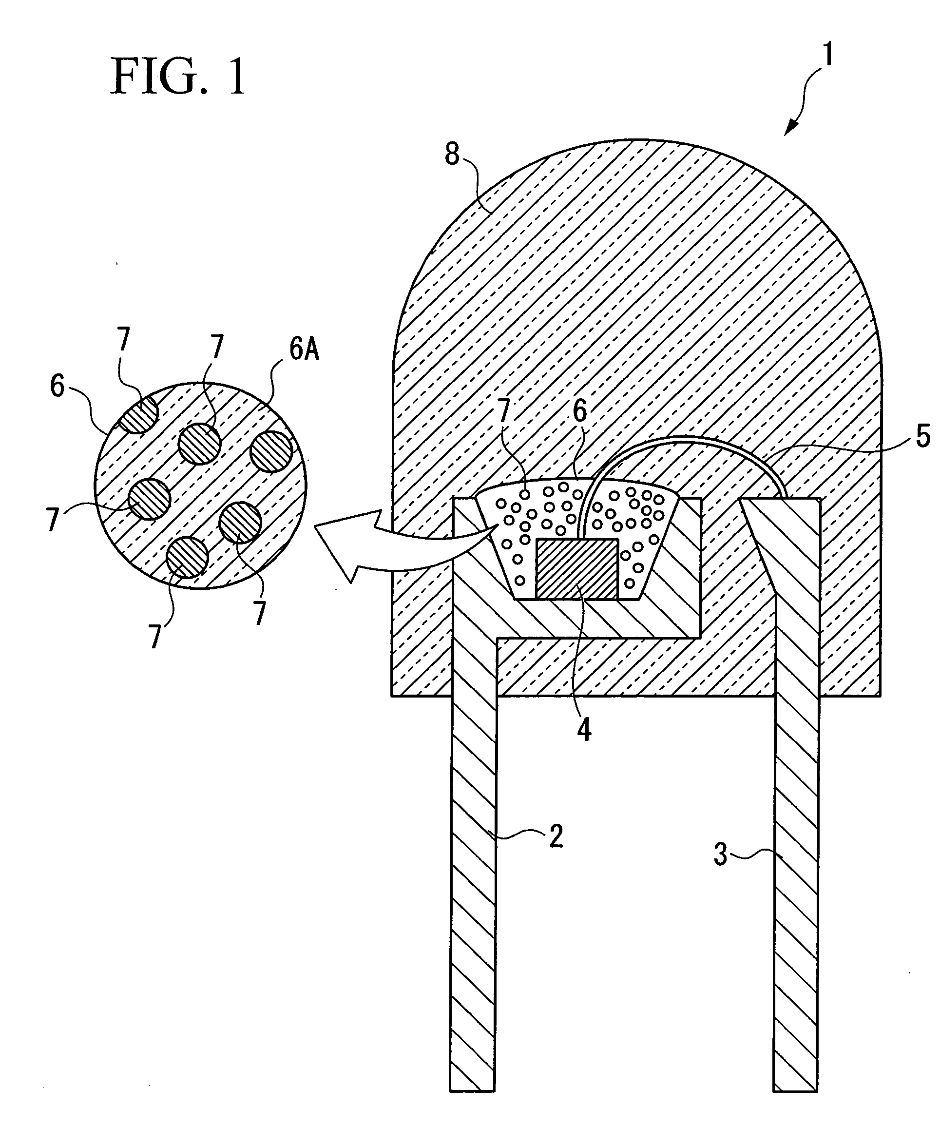
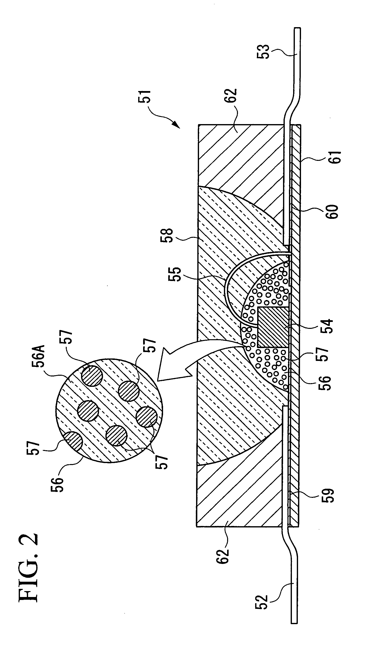
The present invention provides a powdered fluorescent material that can be easily dispersed in a transparent resin and enhance the visible light transmittance of the resin. The powdered fluorescent material has a particle size of 20 μm or less and is excited by visible light. The method for manufacturing the powdered fluorescent material involves sintering a raw material powder and chemically treating it in an acid solution. The powdered fluorescent material can be used in a light-emitting device with a semiconductor light-emitting element, improving the light extraction efficiency and the luminous efficacy of white LED lamps. The present invention also provides an illumination apparatus and an improved method for manufacturing the powdered fluorescent material.

Problems solved by technology

That is, layers with lower luminous efficiency (low efficiency layer) exist on the surface, the luminous efficiency of which is lower than in the inner part of the fluorescent material, and when the particle size is small, the frequency of passage of electron beams through the low efficiency layer increases at high voltages.
As a result, the luminous efficiency cannot be ensured (for instance, refer to “Phosphor Handbook,” Japanese Edition, edited by Phosphor Research Society, 1987, pp.
On the other hand, particles with large size have poor coating properties.
If the transmittance of the fluorescent material-dispersed resin layer in the LED lamp is inadequate, the light extraction efficiency deteriorates.
However, the reflective-type structure is more complex than the conventional structure of white LED lamp, and a large quantity of the fluorescent material becomes necessary, which is also an issue.

Method used


Image

  • Powdered fluorescent material and method for manufacturing the same, light-emitting device, and illumination apparatus
  • Powdered fluorescent material and method for manufacturing the same, light-emitting device, and illumination apparatus
  • Powdered fluorescent material and method for manufacturing the same, light-emitting device, and illumination apparatus

Examples


experiment 1

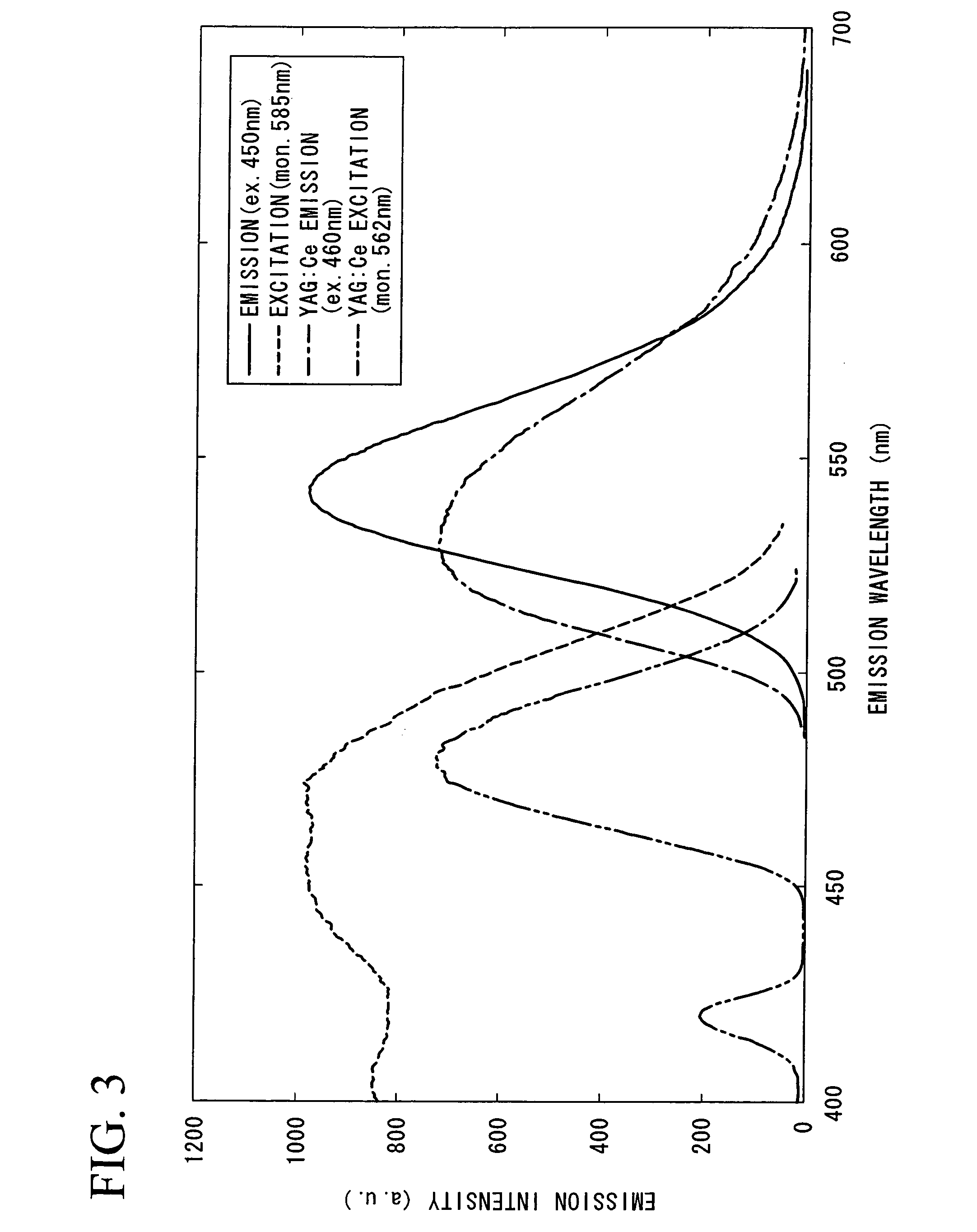
[0131] A commercially available YAG-based fluorescent material that can be expressed by the general formula: (Y,Gd)3Al5O12:Ce and which is commonly known as a fluorescent material for a white LED lamp, was provided. The activation peak wavelength and the light-emitting peak wavelength of this fluorescent material were 468 nm and 563 nm, respectively, and this powder had already been sized into a particle size of less than or equal to 10 μm. The median particle size (median size: the central value of the particle size distribution) of the fluorescent material measured using a laser diffraction / dispersion type particle distribution measuring apparatus was 7.13 μm. Such particles were taken as Sample M. Sample M was dispersed in guaranteed reagent ethanol, and making use of the difference in precipitation speed, the particles were separated into particles of larger size (Sample L) and into particles of smaller size (Sample S).

[0132]FIG. 5 shows particle distributions of Samples S, M, ...

experiment 2

[0136] Three samples (Sample 2A, Sample 2B, and Sample 2C) of an α-SiAlON yellow fluorescent material were prepared by the procedure described below. Each of these samples was used in white LED lamps manufactured for tests and evaluated.

[0137] Calcium α-SiAlON activated by divalent europium is generally expressed by the general formula: CapSi12-(m+n)Alm+nOnN16-n: Eu2+q For this experiment the following values were taken: p=0.875, q=0.0833, and m and n were determined according to p and q as follows: m=1.9999, n=0.99995. Accordingly, the composition was Ca0.875Si9.00015Al2.99985O0.99995N15.00005:Eu2+0.0833.

[0138] Silicon nitride (Si3N4), aluminum nitride (AlN), calcium carbonate (CaCO3), and europium oxide (Eu2O3) were used as the starting materials. According to the composition design mentioned above, 32.570 g of silicon nitride, 9.515 g of aluminum nitride, 6.780 g of calcium carbonate, and 1.135 g of europium oxide were weighed out on an electronic balance so that each batch wei...

experiment 3

[0144] Two samples (Sample FY10-45 and Sample FY10-63) of α-SiAlON yellow powdered fluorescent material were prepared using the procedure described below, and the samples were chemically treated.

[0145] The calcium α-SiAlON activated by this divalent europium, is generally expressed by the general formula: CapSi12-(m+n)Alm+nOnN16-n: Eu2+q For this experiment t following values were taken: p=0.88, q=0.05, and m and n were determined according to p and q as follows: m=1.91, n=0.955. Accordingly, the composition was Ca0.88Si9.135Al2.865O0.955N15.045: Eu2+0.05.

[0146] Silicon nitride (Si3N4), aluminum nitride (AlN), calcium carbonate (CaCO3), and europium oxide (Eu2O3) were used as the starting materials. According to the composition design mentioned above, 33.295 g of silicon nitride, 9.150 g of aluminum nitride, 6.865 g of calcium carbonate, and 0.685 g of europium oxide were weighed out on an electronic balance so that each batch weighed 50 g, and the composition was mixed for 2hours...


PUM

PropertyMeasurementUnit
particle sizesaaaaaaaaaa
median particle sizeaaaaaaaaaa

Abstract

Powdered fluorescent material excited by visible light that emits visible light has particles with particle sizes of 20 μm or less in the content of below 2% by mass. The method for manufacturing a powdered fluorescent material comprises the steps of: sintering raw material powder of the fluorescent material; and chemically processing the sintered powder after said sintering with acid solution.

Description

BACKGROUND OF THE INVENTION [0001] 1. Field of the Invention [0002] The present invention relates generally to a light-emitting device for illumination, and more particularly to a method for manufacturing a powdered fluorescent material for improving the luminous efficacy of powdered fluorescent material provided in said device, powdered fluorescent material with improved luminous efficacy, a light-emitting device with improved luminous efficacy, and an illumination apparatus provided with said light-emitting device. [0003] Priority is claimed on Japanese Patent Application No. 2005-079662, filed Mar. 18, 2005, the content of which is incorporated herein by reference. [0004] 2. Description of Related Art [0005] Conventionally, a light-emitting diode (hereinafter, referred to as “LED”) element emitting light in the short-wavelength range such as blue light, and a white LED lamp, which uses fluorescent element that emits fluorescent light such as yellow light on the long wavelength si...

Claims


Application Information

Patent Timeline
Patent Type & Authority Applications(United States)
IPC IPC(8): H01L29/15G02B5/20H01L31/0256H01L33/30H01L33/50H01L33/54H01L33/56H01L33/60H01L33/62
CPCC04B35/597C04B35/6261C04B2235/3208C04B2235/3224C04B2235/3865C04B2235/3873C04B2235/3895C04B2235/442C04B2235/5436C04B2235/766C09K11/0883C09K11/7734H01L2224/48091H01L2224/48247H01L2924/00014C09K11/77348C09K11/08C09K11/77
Inventor SAKUMA, KENKIMURA, NAOKIOMICHI, KOJIHIROSAKI, NAOTO
Owner THE FUJIKURA CABLE WORKS LTD
Learn More