Novel membrane electrode assembly (MEA) architecture for improved durability for a PEM fuel cell

Inactive Publication Date: 2006-11-23
GM GLOBAL TECH OPERATIONS LLC
View PDF8 Cites 14 Cited by
  • Summary
  • Abstract
  • Description
  • Claims
  • Application Information

AI Technical Summary

Benefits of technology

[0056] One 
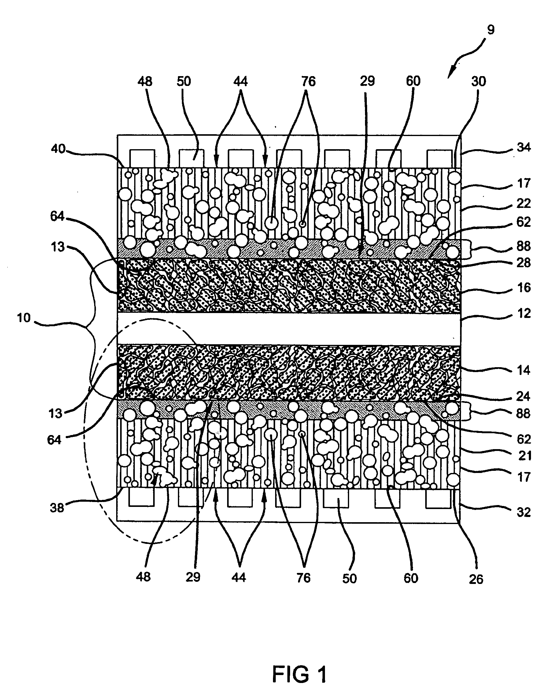
advantage of the present invention relates to water management of the fuel cell. Typically, product water is generated in the fuel cell reaction and rejected at the cathode 16 where the water typically escapes by simple flow or by evaporation. However, means may be provided if desired, for collecting the water as it is formed to carry it away from the fuel cell 9. Good water management enables successful long-term operation of electrochemical fuel cell 9. Spatial variations of water content within the membrane 12 of a current-carrying fuel cell result from the electro-osmotic dragging of water with proton (H+) transport from anode 14 to cathode 16, the production of water by the oxygen reduction reaction at the cathode 16, humidification conditions of the inlet gas stream, and “back-diffusion” of water from cathode 16 to anode 14. Further, for currently employed PEM membranes 12, the optimal efficiency of the fuel cell occurs where the outlet humidity from the cathode is 100% relative humidity or greater. Previously, to achieve this humidity, both the anode 14 and cathode 16 reactant streams were externally humidified prior to entering the fuel cell 9, which necessitated humidification equipment. Maintaining sufficient water content in the fuel cell to prevent drying of the membrane has typically been a significant problem during operations, thus, the inlet streams to both the anode and cathode are humidified, usually to a target of at least 100%.
[0057] One advantage of the present invention relates to eliminating and / or reducing the need for external humidification of the cathode 16 and / or anode 14 inlet stream. It has been discovered that where the fiberless microporous sample (e.g., CARBEL fluid distribution media) was prepared with metallized regions along both sides and used in a fuel cell that was operated to have a typical inlet humidity to the cathode of 100% relative humidity (which is a standard target for cathode inlet humidity), the fuel cell was inundated with excess water and in some circumstances flooded. Thus, in contravention to known prior art, the present invention reduces the need for external humidification of inlet reactant streams to the MEA and provides sustained membrane durability by providing consistent MEA humidification. Methods
[0058] One embodiment of the present invention provides a method for manufacturing an assembly for a fuel cell, comprising depositing an electrically conductive metal on a surface of an electrically conductive fiberless microporous media to form one or more metallized regions having an ultra-thin thickness, wherein the microporous media comprises carbonized expanded-polytetrafluroethylene (ePTFE). The surface having the metallized regions is positioned adjacent to an electrode of a membrane electrode assembly (MEA). The electrode is later contacted with the surface having the metallized regions to form an electrically conductive path between the substrate and the microporous media.
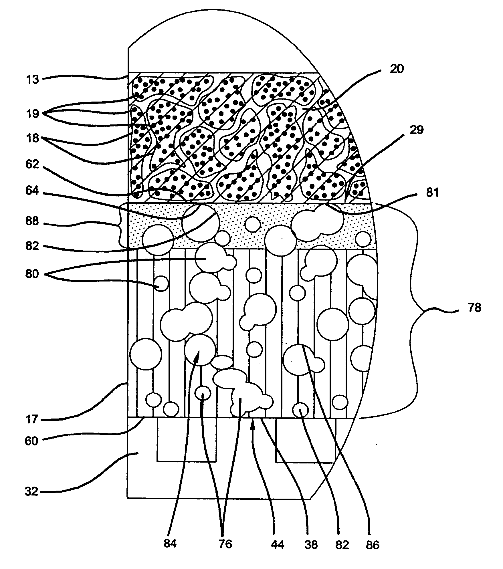
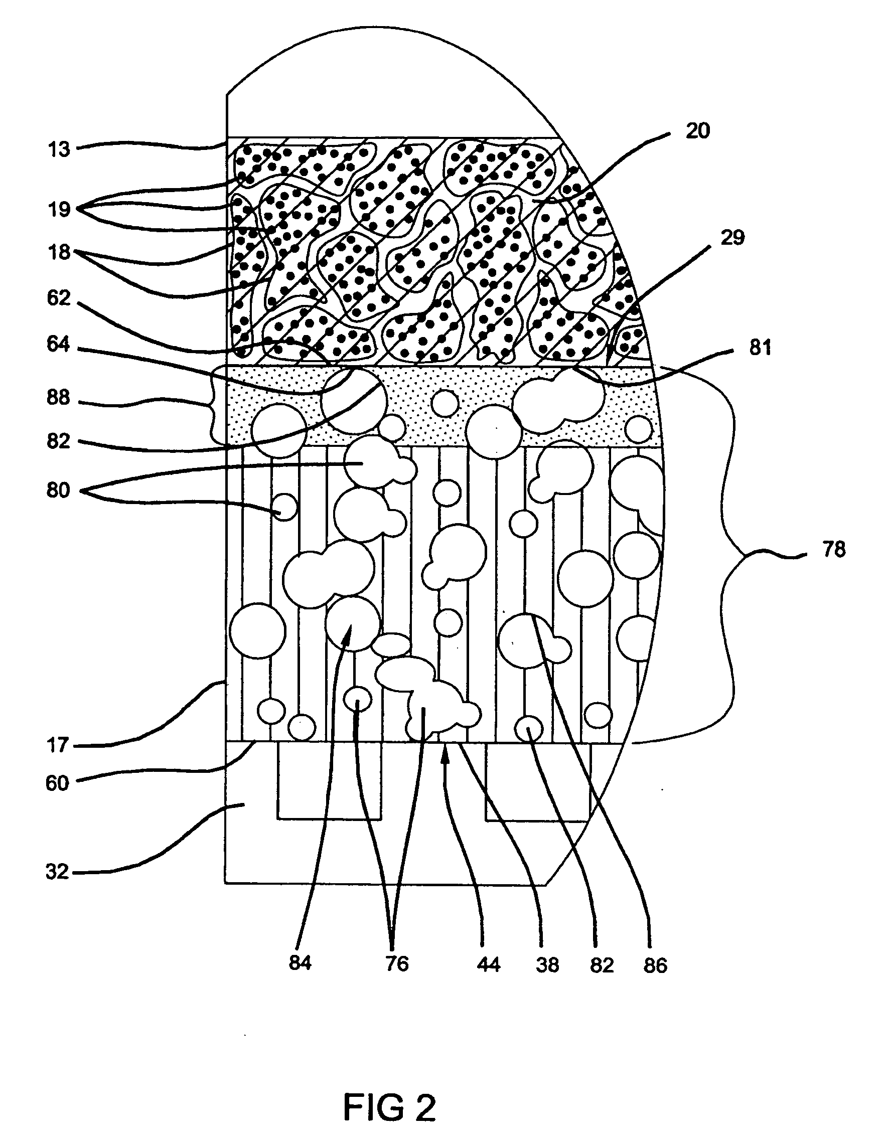
[0059] A variety of depositing methods may be employed to apply the conductive metal compositions that form the metallized regions (e.g., 88, 90, 90a) of the fluid distribution media 17. One preferred method of depositing the conductive metal of the metallized regions 88,90 onto the fluid distribution microporous media 17 is by an ion-assisted, physical vapor deposition (PVD) method, which is well known in the art and described in depth in co-pending and commonly assigned U.S. patent application Ser. No. 10 / 850,550 filed on May 20, 2004, as previously discussed. Noble metals are generally deposited on the substrate by the ion-assisted PVD at a rate of 0.10 nm / s to a thickness of less than 80 nm, which is observed by thickness monitors known in the art. The metallized regions 88, 90, 90a may have conductive metal deposited onto the substrate at ultra-low thicknesses of less than 80 nm, preferably less 40 nm, and most preferably about 2 to about 10 nm. When the metallized region 88,90 has a thickness of at least about 2 nm, it is preferably that the loading is 0.02 mg / cm2. The use of ion-assisted, PVD apparatus allows the electrically conductive metal to be deposited on the substrate very smoothly, evenly, and in an ultra-thin layer on the order of 2 to 20 nm, thereby achieving relatively uniform and good surface coverage, and good adhesion.
[0060] Another preferred PVD method that is also suitable for the application of ultra-thin conductive metals is magnetron sputtering or electron beam evaporation. Other preferred methods of applying a metal coating (88, 90, 90a) according to the present invention include electroplating (e.g. electrolytic deposition), electroless plating, chemical vapor or pulse laser deposition.
[0061] Preferred embodiments of the present invention provide a low contact resistance across the separator plate substrates 32,34 through the microporous media 17 having the metallized regions 88, 90, 90a to the electrodes 13 of the MEA 10. It is preferred that the contact resistance across an entire fuel cell (from separator plate to separator plate) is less than 100 mOhm.cm2 (mΩ.cm2) and more preferably less than 80 mω.cm2 where the several components of the fuel cell are contacted with one another under compressive force. Additionally, under compressive force, any protrusions or sharp edges from the fuel cell components, such as the lands 48 of the separator plates, e.g., 32,34, have the potential to damage the MEA 10. One aspect of the microporous distribution media layer 17 is that it is constructed of a pliable, compressible, and compliant material, such that it protects the MEA 10 from any potential damage and as such, prolongs the lifespan of the fragile MEA 10 by absorbing and distributing any pressure points, while serving as the reactant fluid distribution media 17.

Problems solved by technology

In practice, polymers that fulfill these requirements tend to be relatively fragile and thin, with a typical thickness of approximately 10 to 125 μm.
Such diffusion media generally has the potential for manufacturing flaws, including small protrusions (such as protruding fibers) that may potentially cause damage to the MEA.
Overall, the associated components and assembly contacting the MEA can lead to excessive wear and strain, shortening the lifespan of the fuel cell.

Method used


Image

  • Novel membrane electrode assembly (MEA) architecture for improved durability for a PEM fuel cell
  • Novel membrane electrode assembly (MEA) architecture for improved durability for a PEM fuel cell
  • Novel membrane electrode assembly (MEA) architecture for improved durability for a PEM fuel cell

Examples


example 1

[0069] Experimental details regarding one preferred embodiment of the present invention will now be described in detail. As previously described, CARBEL mp30z is a microporous fiberless carbonized ePTFE having 70% by volume pores, an uncompressed thickness of about 2.5 mils, and is commercially available from the W. L. Gore Company. In the experiment, gold is deposited by ion-asssisted PVD onto the CARBEL by a Teer magnetron sputter system. The CARBEL media is introduced into the vacuum chamber and when the pressure in the vacuum chamber reaches 5×10⁻⁵ the deposition of Au is commenced. The magnetron targets are 99.99% pure Au. The Au deposition is done at −50V bias potential using 0.25 A current for one minute to achieve a gold coating thickness of 10 nm. Au is deposited at a rate of 0.16 nm / s using magnetron sputter system. The thickness of the samples is calibrated using electron probe microanalysis (EPMA). The deposition temperature is preferably about 25° C. to about 30° C.

example 2

[0070] In an alternate method of deposition by electron beam evaporation, the CARBEL mp30z media material, as described above, is introduced into the load lock of an ultrahigh vacuum electron-beam evaporation chamber. After the load lock pressure reaches 10−7 torr, the sample is transferred to the main deposition chamber. The base pressure of the chamber is 5×10⁻⁹ torr. Au is deposited at a rate of approximately 0.05 nm / s using electron-beam evaporation. The rate of deposition is controlled by a quartz crystal microbalance and is calibrated using EPMA. The deposition temperature is preferably about 25 to about 30° C. The quantity of Au deposited can be verified by placing atomically flat single crystal pieces of silicon and simultaneously depositing Au on the silicon and verifying the quantity using the EPMA.

[0071] In FIG. 5, Samples were tested on a 50 cm2 LANL hadware using a Teledyne test stand. Testing was conducted at different cathode inlet relative humidity levels to demonst...


PUM


Abstract

An electrically conductive fluid distribution element for use in a fuel cell having a layer of a conductive non-metallic fiberless microporous media. In certain embodiments, an electrically conductive metal is deposited along a surface of the element to form one or more metallized regions. The metallized regions are arranged to contact a membrane electrode assembly (MEA) in a fuel cell assembly, and thus improve electrical conductance at contact regions between the MEA and the layer of media. Methods of making such a fluid distribution element and operating fuel cell assemblies are also provided.

Description

FIELD OF THE INVENTION [0001] The present invention relates to electrochemical cells, and more particularly to electrically conductive fluid distribution elements and the manufacture and operation of fuel cells incorporating such fluid distribution elements. BACKGROUND OF THE INVENTION [0002] Fuel cells have been proposed as a power source for electric vehicles and other applications. One known fuel cell is the PEM (i.e., Proton Exchange Membrane) fuel cell that includes a so-called “membrane electrode assembly” (MEA) comprising a thin, solid polymer membrane-electrolyte having an anode on one face of the membrane-electrolyte and a cathode on the opposite face of the membrane-electrolyte. A polymer selected for use as a PEM desirably has unique characteristics including permeability to protons and electrical insulation. In practice, polymers that fulfill these requirements tend to be relatively fragile and thin, with a typical thickness of approximately 10 to 125 μm. When adding the...

Claims


Application Information

Patent Timeline
IPC IPC(8): H01M8/02B32B3/26
CPCH01M4/8605Y02E60/521H01M8/1004H01M4/8657Y02E60/50Y10T428/249986Y10T428/24999
Inventor MIKHAIL, YOUSSEF M.VYAS, GAYATRI
Owner GM GLOBAL TECH OPERATIONS LLC
Why Eureka
Try Eureka