Apparatus and method for sizing nanoparticles based on optical forces and interferometric field detection

a nanoparticle and optical force technology, applied in the field of optical force and interferometric field detection, can solve the problems of contamination control of ultrafine particles, difficult detection of nanoparticles, and heritable mutations, and achieve the effect of reducing the number of nanoparticles

Inactive Publication Date: 2007-02-08
UNIVERSITY OF ROCHESTER
View PDF7 Cites 33 Cited by
  • Summary
  • Abstract
  • Description
  • Claims
  • Application Information

AI Technical Summary

Benefits of technology

[0010] To achieve the above and other objects, the present invention is directed to a background-free detection approach which gives us unsurpassed real-time detection sensitivity for nanoscale particles. We demonstrate the successful detection and classification of low-index particles such as individual viruses carried in a microflui

Problems solved by technology

Because of their small size, nanoparticles are not easy to detect, and it is evident that there is high demand in novel techniques for the reliable detection, characterization, sorting, and tracking of nanoscale particles of various sorts.
It has been determined that the inhalation of ultrafine particles originating from emissions of various kinds can cause heritable mutations.
Furthermore, as the feature size of integrated circuits becomes increasingly smaller, contamination control of ultrafine particles poses a challenge for the semiconductor industry.
However, the detection of single nanoparticles is a ch

Method used


Image

  • Apparatus and method for sizing nanoparticles based on optical forces and interferometric field detection
  • Apparatus and method for sizing nanoparticles based on optical forces and interferometric field detection
  • Apparatus and method for sizing nanoparticles based on optical forces and interferometric field detection

Examples


Embodiment Construction

[0018] A preferred embodiment of the present invention will be set forth in detail with reference to the drawings, in which like reference numerals refer to like elements throughout.

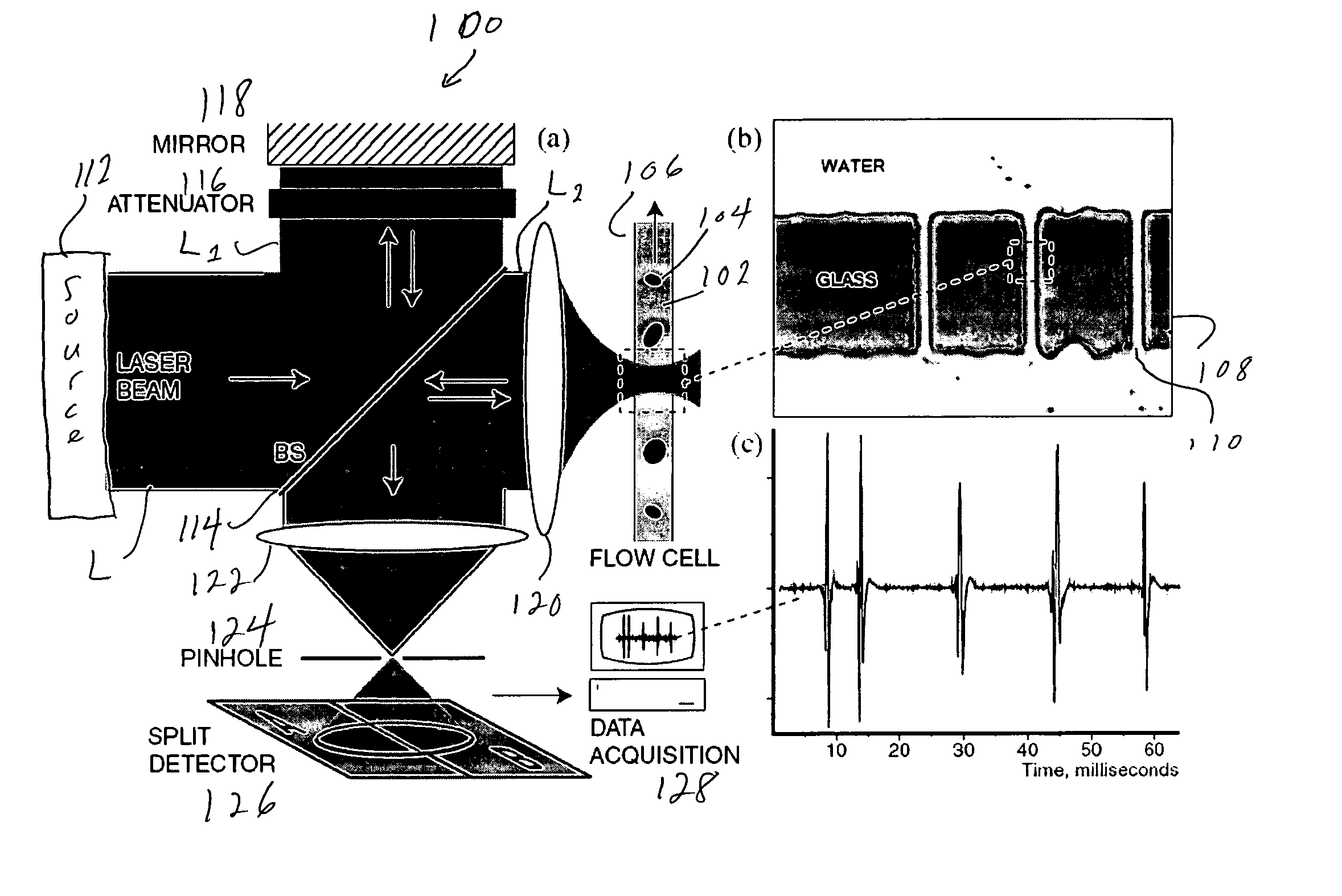
[0019] The detection scheme is schematically shown in FIG. 1 as 100. Using the electro-osmotic effect, as shown in FIG. 1, part (b), a particle solution 102 containing particles 104 is transported through a microfluidic channel 106. The channel 106 is subdivided by a barrier 108 with various nanoscale channels 110. As shown in FIG. 1, part (a), a laser source 112 emits a λ=532 nm laser beam L, which is split by a 50 / 50 beam splitter 114 into two perpendicular paths L1, L2. One path L1 serves as a reference for later interferometric recombination in a reference arm including an attenuator 116 and a mirror 118, and the other path L2 is focused with an objective lens 120 (NA=1.4) into a single preselected nanochannel. In principle, many channels could be sampled sequentially or in parallel by making use of...


PUM


Abstract

Light from a laser source is split into a reference arm and a detection arm. The light in the detection arm is focused into a channel containing particles to be detected and is backscattered by the particles. The light in the reference arm is attenuated. The attenuated and backscattered light are caused to interfere and detected by a split detector so that the effects of background light can be subtracted out, while the backscattered light is detected to detect the particles.

Description

REFERENCE TO RELATED APPLICATION [0001] The present application claims the benefit of U.S. Provisional Patent Application No. 60 / 677,411, filed May 4, 2005, whose disclosure is hereby incorporated by reference in its entirety into the present disclosure.STATEMENT OF GOVERNMENT INTEREST [0002] The work leading to the present invention was supported by NSF Grant No. PHS-0441964 and DARPA Grant No. MDA972-00-1-0021. The government has certain rights in the invention.FIELD OF THE INVENTION [0003] The present invention is directed to a technique for the detection of nanoparticles, such as viruses, and more particularly to an optical technique using interferometry which lessens the dependence on particle radius relative to known techniques. DESCRIPTION OF RELATED ART [0004] Particles with characteristic sizes of less than 100 nm are becoming increasingly important in the context of nanoscience and technology. Applications range from solid-state physics to biology. For example, semiconduct...

Claims


Application Information

Patent Timeline
IPC IPC(8): G01B11/02
CPCB82Y35/00G01N2015/0088G01N2015/0038G01N15/1459
Inventor NOVOTNY, LUKASIGNATOVICH, FILIPP
Owner UNIVERSITY OF ROCHESTER
Why Eureka
Try Eureka