Method of selectable simultaneous/sequential motor drive in a multiple drive circuit including failure detection

a multiple drive circuit and simultaneous/sequential motor technology, applied in the direction of dynamo-electric converter control, dc motor rotation control, multiple dynamo-motor starters, etc., can solve the problem of high noise, poor signal to noise ratio, cross-talk and other sources of noise, etc., to reduce noise sensitivity or significantly reduce the effect of motor current waveform characteristics and noise sensitivity

Active Publication Date: 2007-04-05
APTIV TECH LTD
View PDF18 Cites 18 Cited by
  • Summary
  • Abstract
  • Description
  • Claims
  • Application Information

AI Technical Summary

Benefits of technology

[0016] In accordance with one aspect of the present invention, a method and system for eliminating or significantly reducing the sensitivity to noise and variation in motor current waveform characteristics (e.g. amplitude and shape) caused by, for example, motor aging and dynamic load conditions, is provided. The method and system are not dependent on the high-frequency characteristics of the motor current waveform produced by the rapid change in current during commutation. The method and system use relative maximum and minimum values of motor sinusoidal current levels typically caused by the time-varying back-EMF generated due to the relationship of the rotor position with the magnetic flux, along with adaptive thresholds, to generate pulses representing incremental angular displacement of the rotor used to determine motor shaft position.
[0019] In accordance with still another aspect of the present invention, a method and system for multiplexing external motor drivers to a pulse count driver with a simultaneous drive scheme is provided. The method and system utilize additional discrete circuitry to extend the driver capability of a pulse count driver supporting multiple channels and DC motors, to control additional channels and DC motors, with the ability to drive a plurality of the channels simultaneously.
[0020] In accordance with yet another aspect of the present invention, a method and system for allowing the selectable configuration of a multiple H-bridge driver so that it can be used in either a sequential or simultaneous drive configuration is provided. In the simultaneous mode, all H-bridges will respond to their individual control inputs and work independently of the state of the other H-bridges. In the sequential mode, all H-bridges will share a common bottom side, allowing for elimination of extra wires required in simultaneous driver mode. In this mode, the operation of individual H-bridges will be dependent on the state of the others due to the common bottom side. The driver configuration will be determined by the state of a single serial peripheral interface (SPI) control input bit.

Problems solved by technology

Signal degradation due to brush bounce and other noise caused by motor aging can be a major cause of accuracy and reliability concerns.
Another drawback is the susceptibility of detection circuitry to electromagnetic interference (EMI), cross-talk and other sources of noise.
Detection thresholds must be set to the minimum motor current amplitude, resulting in poor signal to noise ratios and susceptibility to noise in very light load conditions.
In addition, applications using asymmetric (unbalanced) magnetized motors are often sensitive to very light and assisted loads, which can result in very unreliable commutation characteristics requiring prediction techniques to achieve desired accuracy.
Another drawback with using a conventional commutation spike detection scheme for determining the shaft position in DC motors relates to the system voltage level.
An additional drawback with a commutation spike detection scheme occurs when the motor is braked.
This is known as a “false brake pulse”, and results in an error in pulse counting.
Because the control logic that sends the “brake” signal is asynchronous relative to the spike detection circuitry, the inductive kickback due to the shorting of the motor windings in response to a “brake” signal can be detected as a false event, resulting in an error in pulse counting.
Due to motor speed and the processing complexity required to synchronize a brake command with the pulse detection circuitry, implementation of a system to reject false brake pulses can be difficult.
In addition to facing the above-described limitations in detecting and processing signals, developers and manufacturers of systems requiring multiple brush-type DC motors also face problems of controlling the motors with optimum efficiency and cost.
The number of driver channels is typically limited to between 1 and 4 due to the size and cost of the power transistors required for the H-bridge circuits, the number of motors per system, and the number of systems.
It is generally not cost effective to have more than one spare channel driver in a given motor drive circuit or integrated circuit (IC) in the conventional system.
When system requirements dictate the need for more driver channels than are available in a single IC package, the designer is often faced with a tradeoff between using additional ICs and wasting the spare channels (since not all channels on the new IC are needed), or alternatively using more costly discrete driver technology.
While this solution is simple, it is limited in performance because only one motor can be controlled at a time, and also because adding additional drivers increases the total system throughput time.
This situation often typically makes it impossible to take advantage of the low cost of pulse count systems in high-end systems, where throughput is critical to total performance.
Finally, in applications requiring bi-directional control of multiple motor actuators, such as those found in automotive climate control systems, for example, design teams are often faced with making another tradeoff between system cost and system performance.
However, there is a significant impact on the response time which can degrade system performance.
However, this does not allow for selectable configuration of simultaneous or sequential drive operation in a single package.
Therefore, the designer is forced either to have two different driver solutions to meet the challenges of various customers, or to limit itself to a single solution that is either not cost effective and / or of limited performance.

Method used


Image

  • Method of selectable simultaneous/sequential motor drive in a multiple drive circuit including failure detection
  • Method of selectable simultaneous/sequential motor drive in a multiple drive circuit including failure detection
  • Method of selectable simultaneous/sequential motor drive in a multiple drive circuit including failure detection

Examples


third embodiment

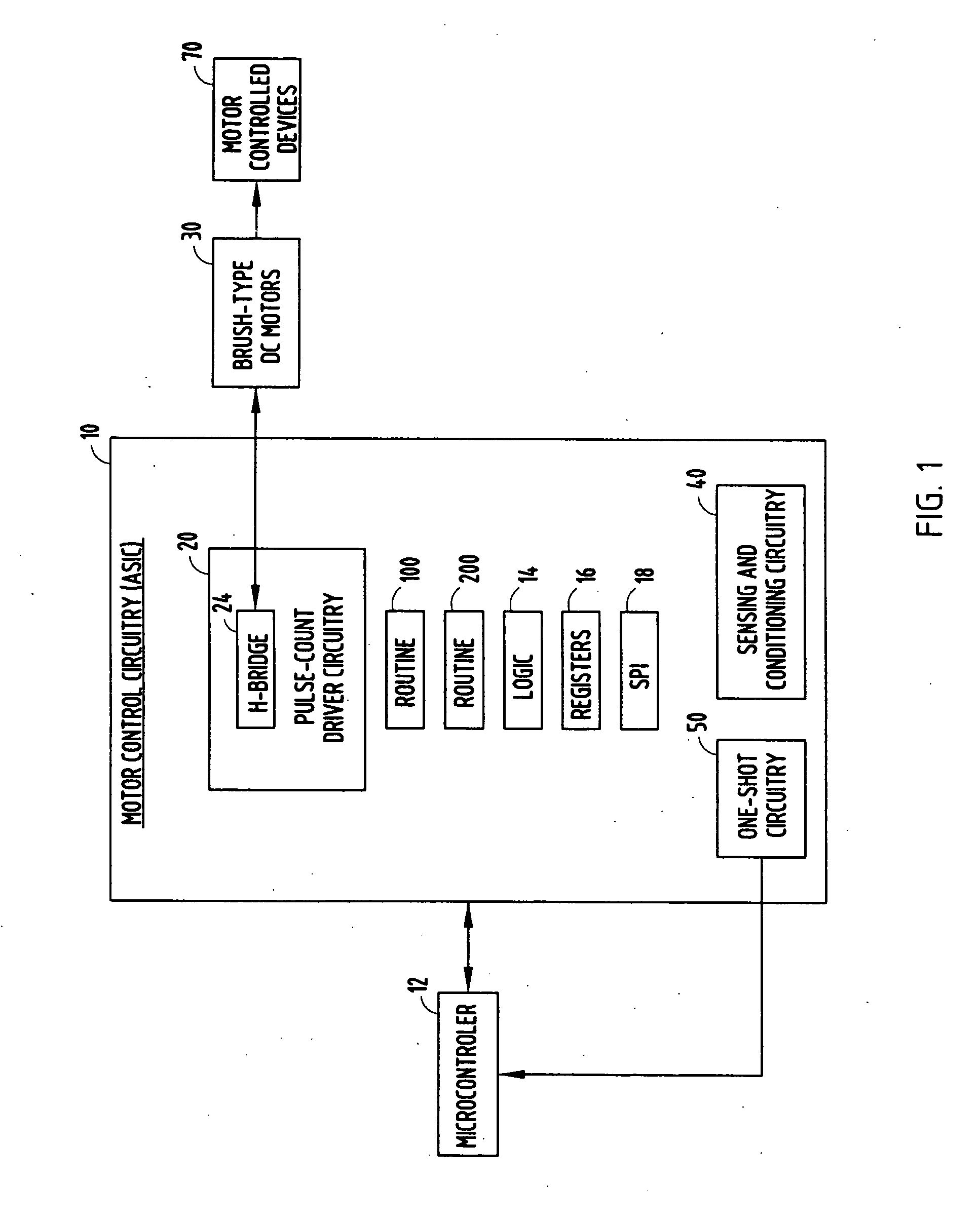
[0075] Referring to FIG. 12, an electric motor control system is generally illustrated, according to the present invention. In this embodiment, the motor control system includes brake filter circuitry 21, in addition to the other elements shown in the embodiment of FIG. 1. It should be appreciated that brake filter circuitry 21 could generally be included in the other embodiments. The motor control system according to this embodiment operates in a manner similar to the embodiment described in FIG. 1, with the added benefit that the motor shaft position detection system is improved by the addition of brake filter circuitry 21, making the system insensitive to the inductive kickback generated by shorting the motor windings when it is commanded to brake. Brake filter circuitry 21 does this by synchronizing the brake command received from microcontroller 12 with a one-shot pulse issued by one-shot circuitry 50.

[0076]FIG. 13 provides an exemplary embodiment of the brake filter circuitry ...

fourth embodiment

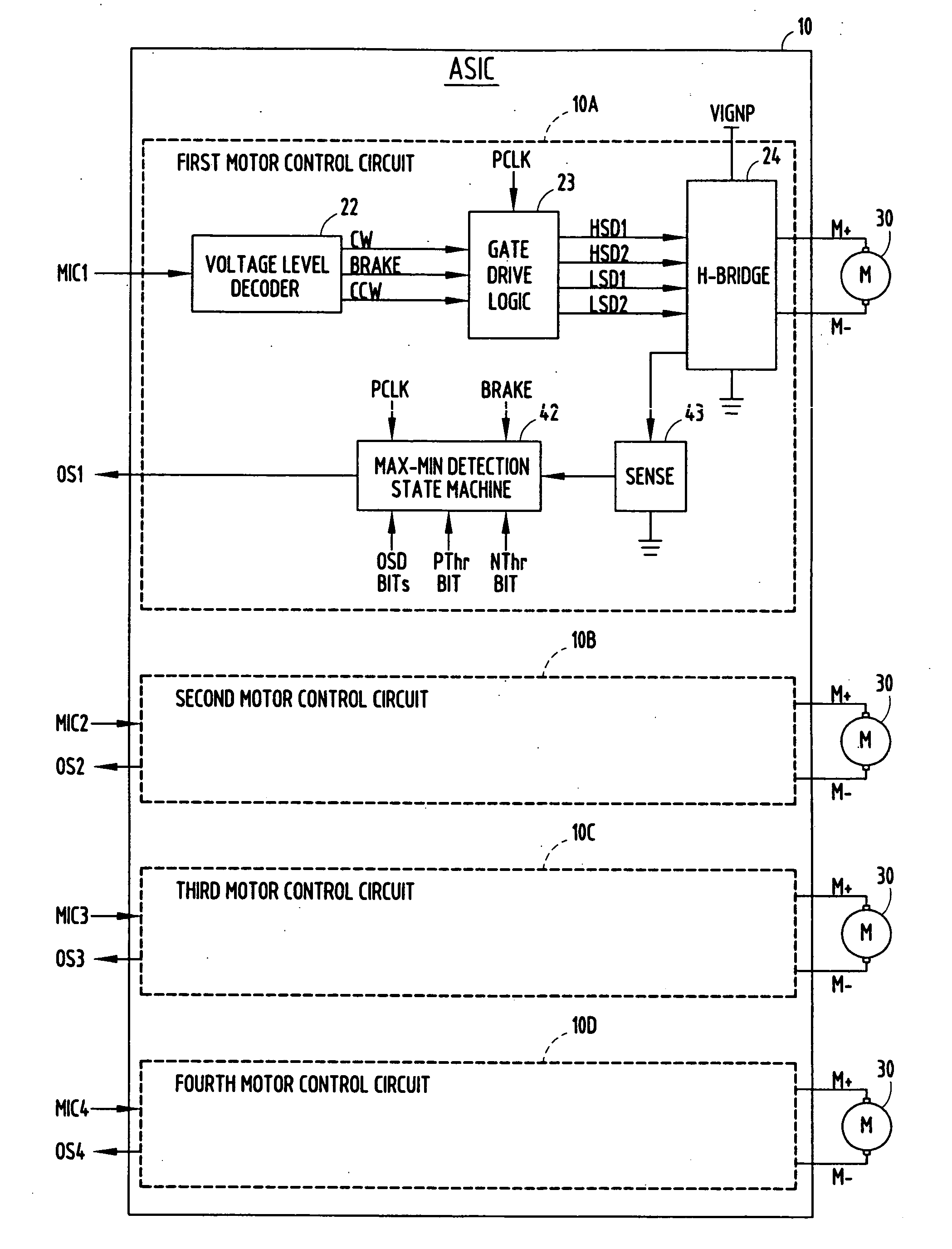
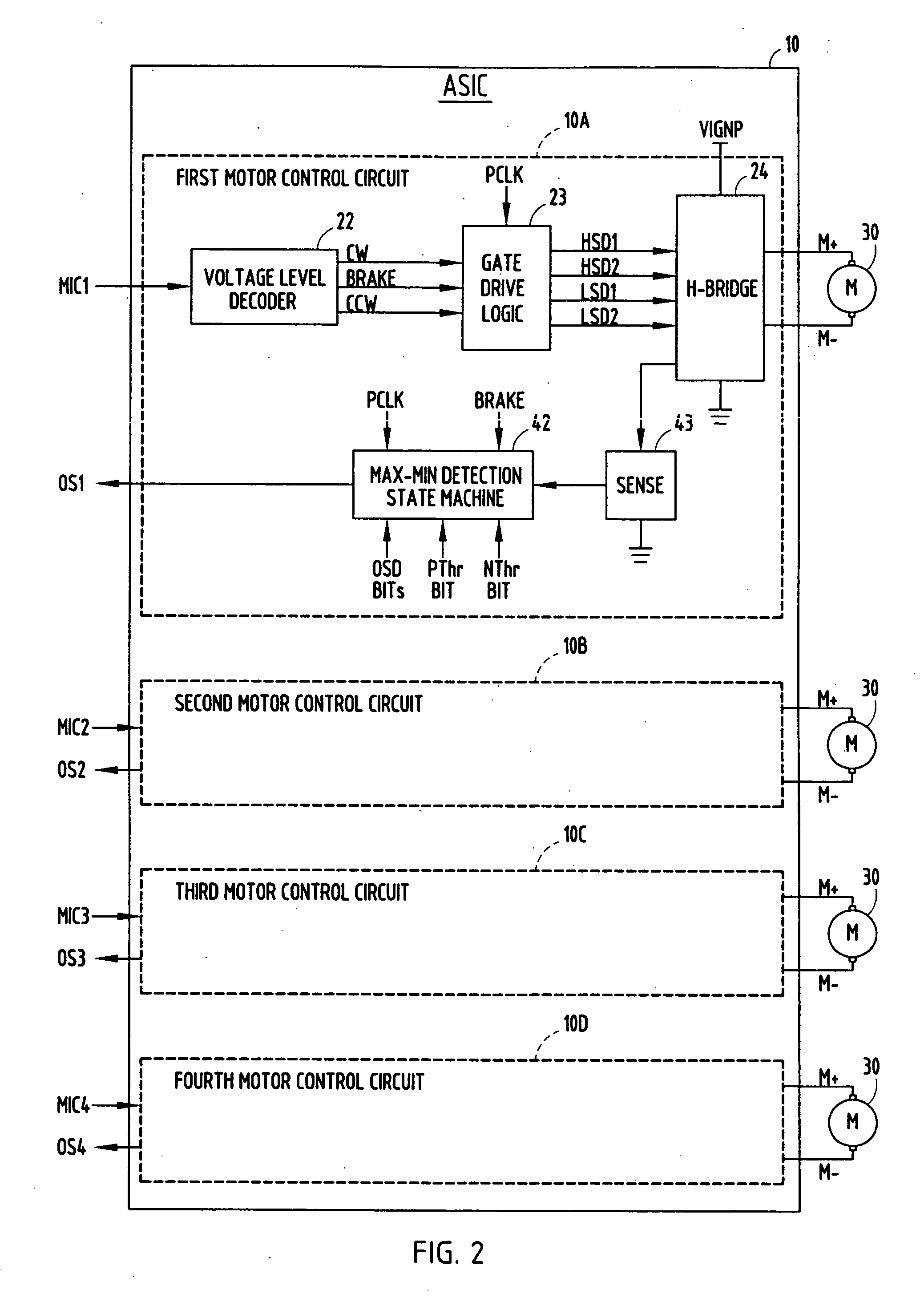
[0079]FIG. 17 illustrates exemplary circuitry for implementing the motor multiplex circuitry in the motor control system, according to the In this implementation, the pulse count motor driver shown as QPC3 includes four full H-bridge driver circuits, four high-side current sensing circuits, and four detection circuits. QPC3 and a microprocessor (corresponding to microcontroller 12 of FIG. 15) are shown connected to motor multiplex circuitry (corresponding to motor multiplex circuitry 60 of FIG. 15) that provides the capability to interface to two additional external motors (Motors 5 and 6 in FIG. 17). In this implementation, channels 3 and 4 of QPC3 are multiplexed with external driver circuitry of fifth and sixth channels, respectively. This motor control system results in the capability of controlling a total of six motors, with up to four motors able to operate simultaneously. In this exemplary configuration, only motor 3 or 5 and / or motor 4 or 6 can be operated at one time. How...

sixth embodiment

[0089]FIGS. 20-21 also illustrate a motor control system according to the present invention. In this embodiment, pulse count driver circuitry 20 can be configured to monitor a bit (CNOP) from microcontroller 12 indicating when microcontroller 12 is not operating properly.

[0090] Pulse count driver circuitry 20 can be configured such that, when it detects a CNOP bit, it will drive all four motors simultaneously in a predetermined direction. When this occurs, each motor 30 is independently driven in the predetermined direction until a stall condition is detected or until a master timeout event occurs. During this mode of operation, motor commutations are independently detected for each of the motors 30 for stall detection. FIG. 22 illustrates a state definition matrix for the FETs of drive circuitry in the embodiment shown in FIGS. 20 and 21 utilizing a quad pulse count driver integrated circuit configured to simultaneously drive all four motors in a predetermined direction when an SPI...


PUM


Abstract

A system and method is provided for improved monitoring and controlling of mechanically commutated DC motors. The system and method include DC motors, pulse-count driver circuitry for driving the motors, motor position sensing circuitry, and motor control circuitry. The system and method provide for improved motor current waveform sensing that is able to effectively reject false brake pulses, avoid erroneous processing due to fluctuating battery voltage levels, and reduce the sensitivity to variations in motor current signals due to dynamic motor load, manufacturing variation, system aging, temperature, brush bounce, EMI, and other factors. The system and method also include an improved ability to multiplex additional external motor drivers to the motor control circuitry, select between sequential and simultaneous drive modes using an SPI bit, and monitor the system controller for an error condition and simultaneously driver motors in response to the error condition.

Description

CROSS-REFERENCE TO RELATED APPLICATION [0001] This application claims the benefit under 35 U.S.C. § 119(e) of U.S. Provisional Application No. 60 / 723,391, filed on Oct. 4, 2005, the entire disclosure of which is hereby incorporated herein by reference.TECHNICAL FIELD [0002] The present invention generally relates to the control of electric motors, and more particularly, to effective and efficient monitoring and control of brush-type DC motors. BACKGROUND OF THE INVENTION [0003] As technology has progressed, the use of electric motors to perform numerous tasks previously accomplished manually has increased dramatically. For example, a simple manual task like rolling down a vehicle window is performed by the simple push of a button, with a motor performing the actual work of rolling down the window. The manual action of opening or closing car vents to redirect hot or cold air to various locations is performed simply by changing a temperature setting on a control panel. Examples of the...

Claims


Application Information

Patent Timeline
Patent Type & Authority Applications(United States)
IPC IPC(8): H02P5/46
CPCH02H7/0811H02P5/68H02P7/0044H02P7/29H02P7/0094H02P7/04
Inventor MOLLER, DAVIDSCHNEIDER, PHILIPBERRYMAN, DENNIS
Owner APTIV TECH LTD
Why Eureka
Try Eureka