
Electrode for energy storage device and process for producing the same

Inactive Publication Date: 2007-05-31
YAMAGUCHI UNIV +1
View PDF9 Cites 4 Cited by
  • Summary
  • Abstract
  • Description
  • Claims
  • Application Information

AI Technical Summary

Benefits of technology

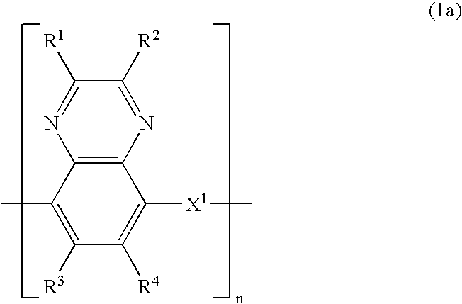
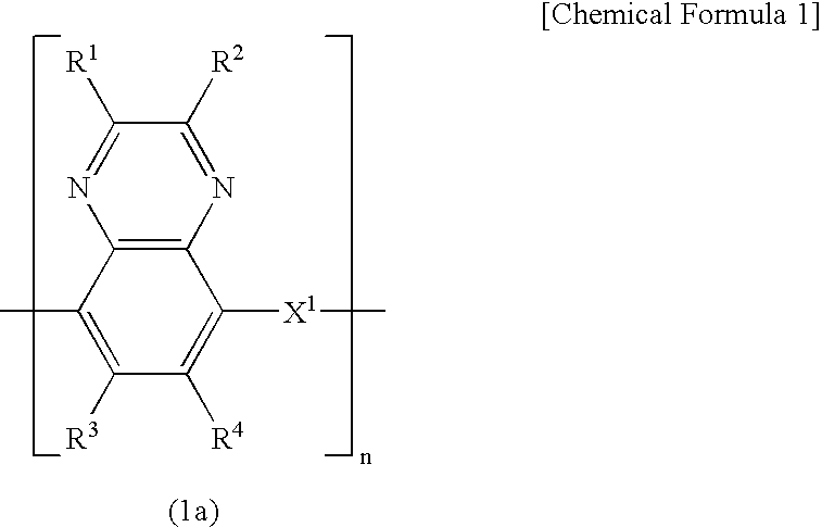
[0026] The polyaminoquinoxaline compounds of the formulae (1a) to (1d) used as an electrode active material of an electrode for an energy storage device according to the invention have a good heat resistance and is readily controllable with respect to the electrochemical redox potential thereof involving proton movement, and have good cyclic properties.
[0027] Moreover, these polyaminoquinoxaline compounds have an electron donative group and an electron acceptive group in one molecule, and are those conductive polymer compounds which not only can be used as either of a positive electrode or a negative electrode, but also exhibit a wide potential activity.
[0028] The device that is arranged as having an electrode for an energy storage device of the invention using a polyaminoquinoxaline compound as an electrode active material ensures storage at high capacitance.
[0029] Especially, when the polyaminoquinoxaline compound is used as an electrode for an electric double layer capacitor, the redox reaction of the electrode active material and the electric double layer occurring on the surface of the electrode both function as an energy source, so that storage of a higher capacitance is enabled than in a conventional electric double layer capacitor using active carbon alone.

Problems solved by technology

Thus, when using only the procedure of trying to increase the specific surface area of a porous material, limitation is placed on the increase of the electrostatic capacitance of an electric double layer capacitor, thus making it difficult to attain the high densification of an energy to a level required in recent years (see Patent Document 1: JP-A 11-317333 and Patent Document 4: JP-A 11-297577).
Thus, it is generally difficult to make a polymer cell or capacitor which works at high voltage.
However, since this energy storage device needs to use different types of molecules in the positive and negative electrodes as set out hereinabove, this is defective from the standpoint of productivity.

Method used


Image

  • Electrode for energy storage device and process for producing the same
  • Electrode for energy storage device and process for producing the same
  • Electrode for energy storage device and process for producing the same

Examples


synthetic example 1

Synthesis of 2,3-dihydroxy-5-aminoquinoxaline

[0074] Prepared according to the following procedures (1) to (3).

(1) Synthesis of 2,3-diaminonitrobenzene

[0075] 14 g of commercially available 1-amino-2,5-dinitrobenzene was dissolved in 225 ml of methanol, to which a solution of 60 g of sodium sulfide and 21 g of sodium hydrogen carbonate dissolved in 240 g of water was added by use of a dropping funnel while keeping the reaction temperature at 60° C. After completion of the addition, agitation was continued at 60° C. for 1 hour. After completion of the reaction, the mixture was cooled down to room temperature and filtered.

[0076] m / z: (FD+) 153 (calculated 153.1396) 1H-NMR: 7.7228, 7.7203, 7.7206, 7.2433, 6.9245, 6.6209, 6.6063, 6.6038, 6.5886, 5.9210, 3.3978 ppm Yield: 7.79 g (66.5%) Product aspect: Reddish brown fine crystals Melting point: 140° C.

(2) Synthesis of 2,3-dihydroxy-5-nitroquinoxaline

[0077] 4 g (26.12 mmol) of 2,3-diaminonitrobenzene and 6.59 g (52.24 mmol) of com...

synthetic example 2

Synthesis of 2,3-diphenyl-5-aminoquinoxaline

[0081] Prepared according to the following procedures (1) and (2).

(1) Synthesis of 2,3-diphenyl-5-aminoquinoxaline

[0082] 1.53 g (10 mmol) of 2,3-diaminonitrobenzene and 2.00 g (9.6 mmol) of benzil were placed in four-necked flask, to which 30 g of a solvent of acetic acid and methanol at a mixing ratio of 1:1 was added for dissolution. Subsequently, the mixture was reacted at a reaction temperature of 70° C. for 2 hours. After the reaction, the solvent was removed and the resulting product was extracted with a silica gel column (ethyl acetate:hexane=1:1).

[0083] Yield: 2.11 g Product aspect: Yellow fine crystals m / z: 327 (calculated 327.24)

(2) Synthesis of 2,3-diphenyl-5-aminoquinoxaline

[0084] 1.04 g of 2,3-diphenyl-5-nitroquinoxaline was dissolved in 30 g of dioxane, followed by purging with argon and further addition of 0.5 g of 5% Pd / C (hydrous). After sufficient purging with argon again, hydrogen was added and reacted at room ...

synthetic example 3

Synthesis of 2,3-di(4-methylphenyl)-5-aminoquinoxaline

[0086] Prepared according to the following procedures (1) and (2).

(1) Synthesis of 2,3-di(4-methylphenyl)-5-nitroquinoxaline

[0087] 1.84 g (12 mmol) of 2,3-diaminonitrobenzene and 2.38 g (10 mmol) of 4,4′-dimethylbenzil were dissolved in 40 g of a mixed solvent of acetic acid and methanol (1:1) and reacted at a reaction temperature of 80° C. for 4 hours. After completion of the reaction, the solvent was removed and the resulting reaction product was extracted by means of a silica gel column.

[0088] Yield: 1.30 g Product aspect: Yellow fine crystals m / z: 355 (calculated 355.39) 13C-NMR: 154.8950, 154.8339, 147.0894, 140.7563, 140.1307, 139.8636, 135.5984, 135.1253, 133.7061, 133.2254, 130.2725, 129.7003, 129.3188, 129.1204, 128.4108, 127.7470, 124.2142 ppm

(2) Synthesis of 2,3-di(4-methylphenyl)-5-aminoquinoxaline

[0089] 2.02 g of 2,3-di(4-methylphenyl)-5-nitroquinoxaline was dissolved in 30 g of dioxane, followed by purging...


PUM

PropertyMeasurementUnit
Timeaaaaaaaaaa
Timeaaaaaaaaaa
Weightaaaaaaaaaa

Abstract

An electrode for an energy storage device containing a polyaminoquinoxaline compound of the following formula (1a) is provided as having a highly densified energy level and being small in size and light in weight. R1 and R2 independently represent a hydrogen atom, a hydroxyl group, a C1-C10 alkyl group, a C1-C10 alkoxy group or the like, R3 and R4 independently represent a hydrogen atom, a halogen atom, a cyano group, a nitro group, an amino group, a C1-C10 alkyl group, a C1-C10 alkoxy group or the like, X1 represents —NH—R5—NH— or —NH—R6— wherein R5 and R6 independently represent a C1-C10 alkylene group, —C(O)CH2—, —CH2C(O)— or the like, and n is an integer of 2 or over.

Description

TECHNICAL FIELD [0001] This invention relates to an electrode for energy storage device and also to a method for making the same. More particularly, the invention relates to an electrode for energy storage devices containing an aminoquinoxaline polymer as an active material for the electrode and the manufacture thereof. BACKGROUND ART [0002] An electric double layer capacitor that is known as one of energy storage devices is generally constituted of a pair of polarizable electrodes each containing a porous material, a separator, an electrolyte solution and the like. This electric double layer capacitor is a device which makes use, as a charge and discharge mechanism, of an electric energy ascribed to the electric double layer established through ionic movement at the interface between the electrodes. Because no electrochemical reaction of an electrode active material is involved, the capacitor does not have such a life as of secondary cells, along with characteristic features includ...

Claims


Application Information

Patent Timeline
IPC IPC(8): H01L51/00C08G73/06C08G61/12H01G9/00H01G11/22H01G11/48H01G11/86H01M4/02H01M4/60
CPCC08G61/122C08G73/0694H01G9/155Y02E60/13H01M4/60H01M4/606H01M4/02Y02E60/10H01G11/48H01G11/02C08G73/00H01G9/00
Inventor MORITA, MASAYUKIYOSHIMOTO, NOBUKOMUKAI, YASUAKIKASAI, MIKIOFURUSHO, HITOSHI
Owner YAMAGUCHI UNIV
Features
  • Generate Ideas
  • Intellectual Property
  • Life Sciences
  • Materials
  • Tech Scout
  • Unparalleled Data Quality
  • Higher Quality Content
  • 60% Fewer Hallucinations
Learn More