Resin composition for ghz-band electronic component and ghz-band electronic component
a technology of electronic components and resins, applied in the direction of high-frequency circuit adaptations, conductors, transportation and packaging, etc., can solve the problems that nanoscale carbon tubes cannot be added to resins for high-frequency electronic components in a large amount, and that no attempt has been made to reduce the dielectric loss tangent in high-frequency bands using nanoscale carbon tubes, etc., to achieve high mechanical strength, high heat resistance, and loss tangent
- Summary
- Abstract
- Description
- Claims
- Application Information
AI Technical Summary
Benefits of technology
Problems solved by technology
Method used
Image

Examples
reference example 1
Production of Amorphous Nanoscale Carbon Tubes
[0195] Amorphous nanoscale carbon tubes were produced by the following process.
[0196] Ten milligrams of an anhydrous iron chloride powder (particle diameter: not more than 500 μm) was uniformly sprinkled over a PTFE film (60 μm×10 mm×10 mm), and subjected to plasma excitation. The plasma excitation conditions were as follows. [0197] Atmosphere: argon (Ar) [0198] Internal pressure: 0.01 torr [0199] Input power: 300 W [0200] RF frequency: 13.56 MHz
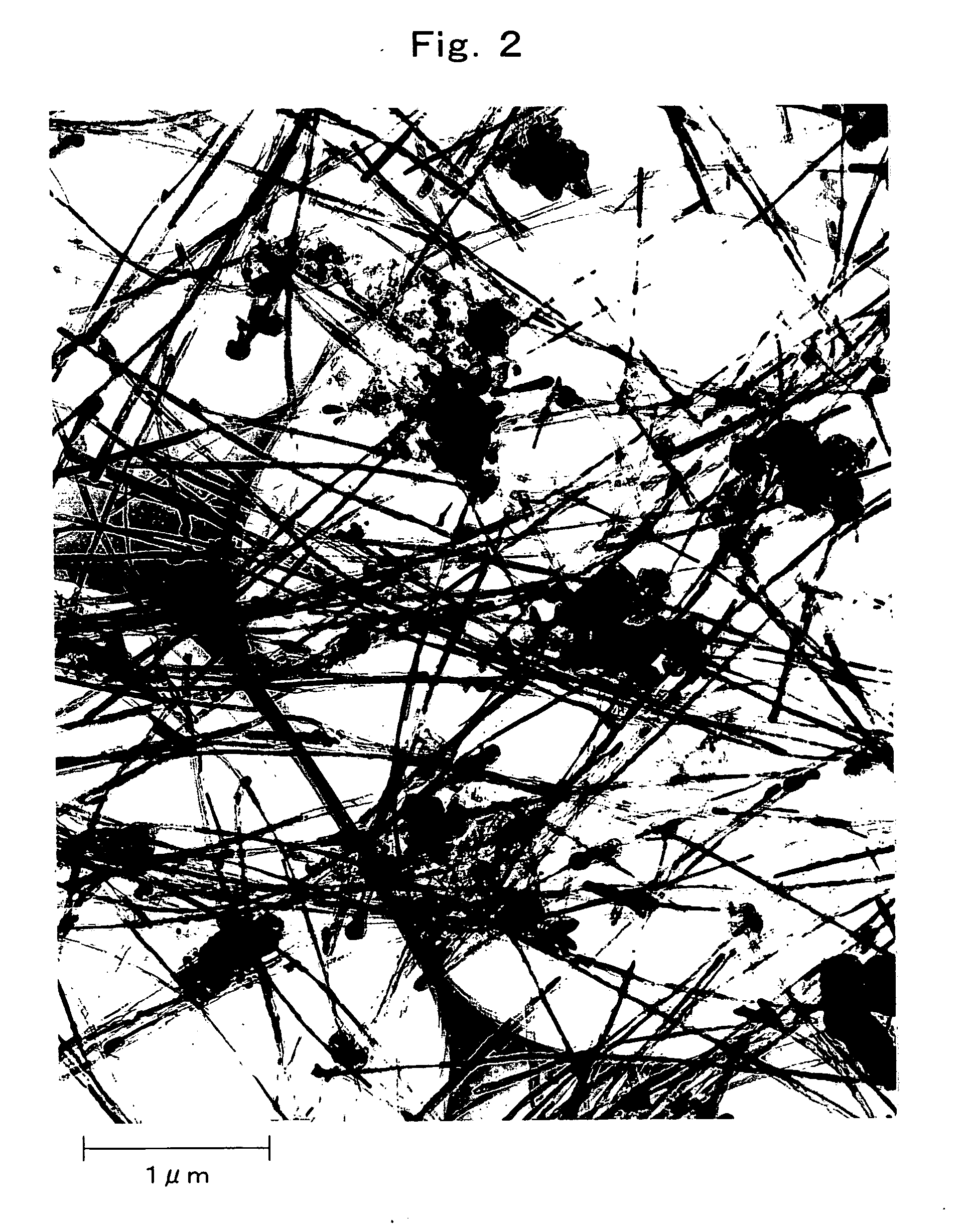
[0201] After the reaction, the formation of amorphous nanoscale carbon tubes (outer diameter: 10-60 nm, length: 5-6 μm) was confirmed by scanning electron microscopy (SEM) and X-ray diffraction.
[0202] The X-ray diffraction angle (2θ) of the obtained amorphous nanoscale carbon tubes was 19.1 degrees, the hexagonal carbon layer spacing (d002) calculated therefrom was 4.6 Å, and the 20 band half-width was 8.1 degrees.
reference example 2
[0203] Using toluene as a raw material and ferric chloride as a catalyst, a reaction was carried out according to the process described in Japanese Unexamined Patent Publication No. 2002-338220, to thereby obtain a carbonaceous material comprising iron-carbon composites which are composed of nanoflake carbon tubes having internal spaces partially filled with iron carbide.
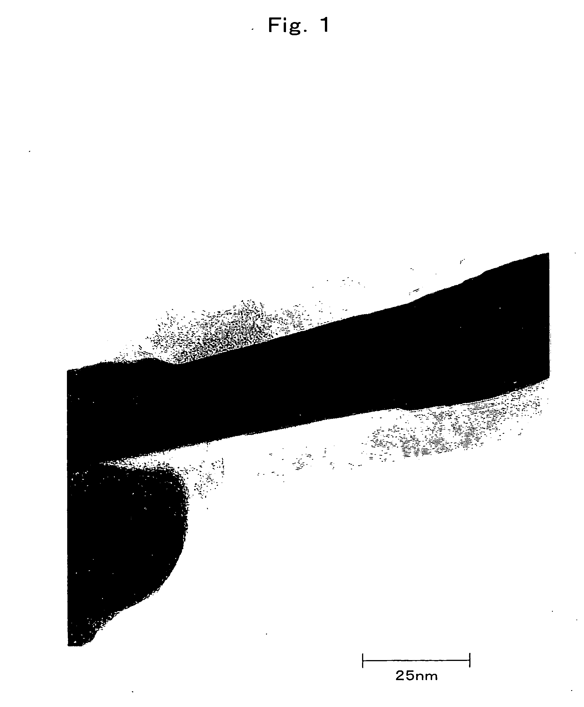
[0204] SEM observation revealed that the obtained iron-carbon composites had an outer diameter of 20 to 100 nm and a length of 1 to 10 microns, and had a highly straight shape. The thickness of the tube walls made of carbon was 5 to 40 nm, and the thickness was substantially uniform over the entire length of each tube. TEM observation showed that the carbon walls did not have a nested or scroll form, and instead had a patchwork-like (so-called papier-mache like) form; and X-ray diffractometry confirmed that the carbon tubes were nanoflake carbon tubes having a graphite structure in which the mean distance between t...
reference example 3
[0207] One gram of the iron-carbon composites obtained in Reference Example 2 (nanoflake carbon tubes partially filled with iron carbide) was dispersed in 100 ml of 1N hydrochloric acid, and the dispersion was stirred at room temperature for 6 hours, followed by filtration. The same procedure was repeated twice using 100 ml of 1N hydrochloric acid to thereby obtain empty nanoflake carbon tubes.
[0208] The obtained nanoflake carbon tubes had substantially the same form, external shape, length and wall thickness as the iron-carbon composites obtained in Reference Example 2. TEM observation showed that the carbon walls did not have a nested or scroll form, and instead had a patchwork-like (so-called papier-mäché-like) form; and X-ray diffractometry confirmed that the carbon tubes were nanoflake carbon tubes having a graphite structure in which the mean distance (d002) between the hexagonal carbon layers was not more than 0.34 nm.
PUM
| Property | Measurement | Unit |
|---|---|---|
| Fraction | aaaaa | aaaaa |
| Angle | aaaaa | aaaaa |
| Angle | aaaaa | aaaaa |
Abstract
Description
Claims
Application Information
 - R&D
- Intellectual Property
- Life Sciences
- Materials
- Tech Scout
- Unparalleled Data Quality
- Higher Quality Content
- 60% Fewer Hallucinations
Browse by: Latest US Patents, China's latest patents, Technical Efficacy Thesaurus, Application Domain, Technology Topic, Popular Technical Reports.
© 2025 PatSnap. All rights reserved.Legal|Privacy policy|Modern Slavery Act Transparency Statement|Sitemap|About US| Contact US: help@patsnap.com