Liquid crystal display device and manufacturing method thereof

a technology of liquid crystal display and manufacturing method, which is applied in the direction of identification means, instruments, roller massage, etc., can solve the problems of extreme deterioration of characteristics, development of phenomenon referred to as reverse gradation, and problems, so as to increase productivity, increase production cost, and improve yield

Inactive Publication Date: 2007-06-28
SEMICON ENERGY LAB CO LTD
View PDF88 Cites 80 Cited by
  • Summary
  • Abstract
  • Description
  • Claims
  • Application Information

AI Technical Summary

Benefits of technology

[0019] Conventionally, TFTs are manufactured on a substrate by a photolithography technique using a minimum of 5 or more photomasks for an active matrix type electro-optical devic

Problems solved by technology

However, with the above TN mode, the contrast characteristics deteriorate extremely outside a specific viewing range, and a problem of a phenomenon referred to as reverse gradation develops.
Small differences in the contact of the brush tip during the rubbing process become a cause of wavy display, which easily becomes a problem.
Further, the rub

Method used


Image

  • Liquid crystal display device and manufacturing method thereof
  • Liquid crystal display device and manufacturing method thereof
  • Liquid crystal display device and manufacturing method thereof

Examples


embodiment 1

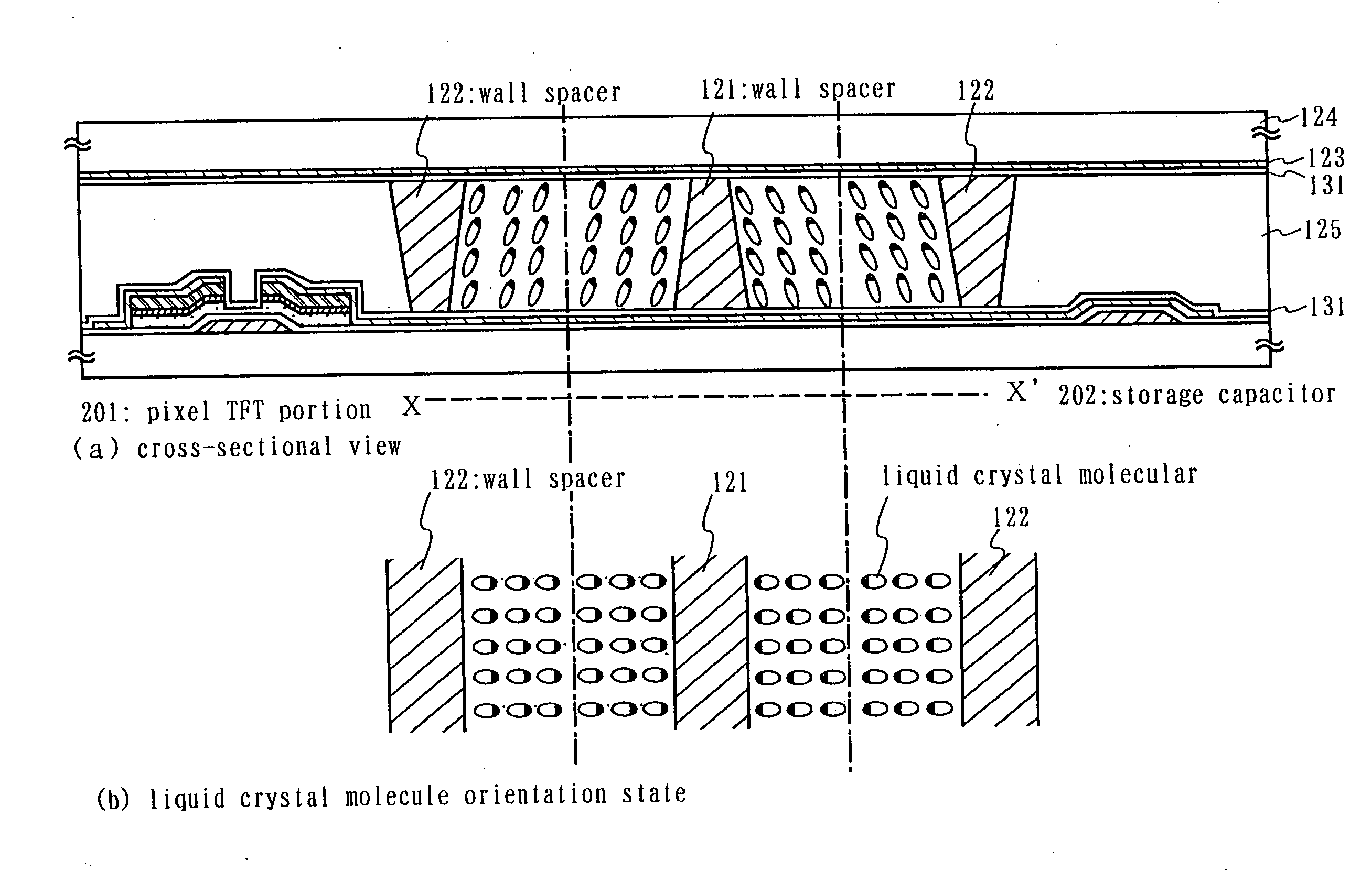
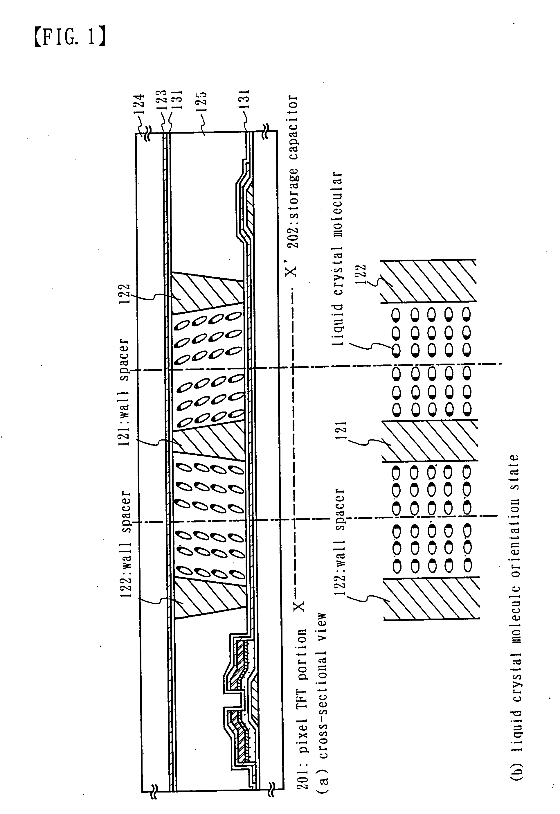
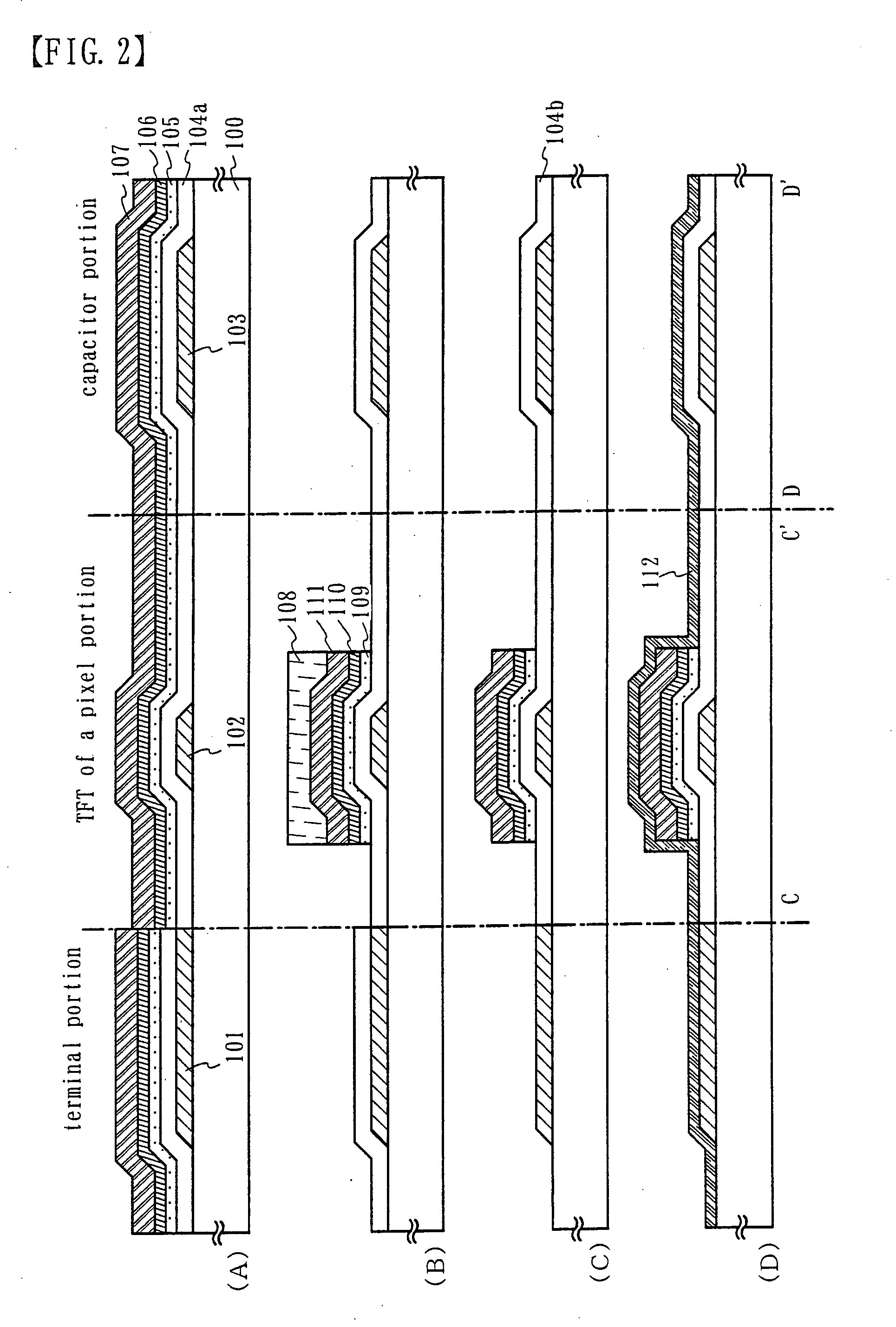
[0129] An embodiment of the invention is explained using FIGS. 1 to 7, 9 and 17. Embodiment 1 shows a method of manufacturing a liquid crystal display panel, and a detailed explanation of a method of forming a TFT of a pixel portion on a substrate by a reverse stagger type TFT, and manufacturing a storage capacitor connected to the TFT, is made in accordance with the processes used. Further, a manufacturing process for a terminal section, formed in an edge portion of the substrate, and for electrically connecting to wirings of circuits formed on other substrates, is shown at the same time in the same figures.

[0130] In FIG. 2(A), a glass substrate, comprising such as barium borosilicate glass or aluminum borosilicate glass, typically Corning Corp. #7059 or #1737, can be used as a substrate 100 having translucency. In addition, a translucent substrate such as a quartz substrate or a plastic substrate can also be used.

[0131] Next, after forming a conductive layer on the entire surfac...

embodiment 2

[0167]FIG. 8 is an example of a method of mounting a liquid crystal display device. The liquid crystal display panel has an input terminal portion 302 formed in an edge portion of a substrate 301 on which TFTs are formed, and as shown by embodiment 1, this is formed by a terminal 303 formed from the same material as a gate wiring. An opposing substrate 304 is joined to the substrate 301 by a sealant 305 encapsulating spacers 306, and in addition, polarizing plates 307 and 308, and a color filter (not shown) are formed. This is then fixed to a casing 321 by spacers 322.

[0168] Note that the TFT obtained in Embodiment 1 having an active layer formed by an amorphous semiconductor film has a low electric field effect mobility, and only approximately 1 cm2 / Vsec is obtained. Therefore, a driver circuit for performing image display is formed by an IC chip, and mounted by a TAB (tape automated bonding) method or by a COG (chip on glass) method. In Embodiment 2, an example is shown of formin...

embodiment 3

[0171] In this Embodiment, an example of forming a liquid crystal display panel by forming a protecting film is shown in FIG. 14. Note that this Embodiment is identical to Embodiment 1 through the state of FIG. 3(B), and therefore only points of difference are explained. Further, the same symbols are used for locations corresponding to those in FIG. 3(B).

[0172] After first forming through the state of FIG. 3(B) in accordance with Embodiment 1, a thin inorganic insulating film is formed on the entire surface. An inorganic insulating film formed by using plasma CVD or sputtering such as a silicon oxide film, a silicon nitride film, a silicon oxynitride film, or a tantalum oxide film is used as the thin inorganic insulating film, and a single layer or a lamination structure made from these materials may be formed.

[0173] A forth photolithography process is performed next, forming a resist mask, and unnecessary portions are removed by etching, forming an insulating film 402 in the pixe...


PUM


Abstract

An electro-optical device typified by an active matrix type liquid crystal display device, is manufactured by cutting a rubbing process, and in addition, a reduction in the manufacturing cost and an improvement in the yield are realized by reducing the number of process steps to manufacture a TFT. By forming a pixel TFT portion having a reverse stagger type n-channel TFT, and a storage capacitor, by performing three photolithography steps using three photomasks, and in addition, by having a uniform cell gap by forming wall-like spacers by performing one photolithography step, without performing a rubbing process, a multi-domain perpendicular orientation type liquid crystal display device having a wide viewing angle display, and in which a switching direction of the liquid crystal molecules is controlled, can be realized.

Description

BACKGROUND OF THE INVENTION [0001] 1. Technical Field to Which the Invention Belongs [0002] The present invention relates to a semiconductor device having a circuit composed of a thin film transistor (hereafter referred to as TFT), and to a method of manufacturing thereof. For example, the present invention relates to an electro-optical device, typically a liquid crystal display panel, and to electronic equipment loaded with this type of electro-optical device as a part. [0003] 2. Prior Art [0004] In recent years, techniques of structuring a thin film transistor (TFT) by using a semiconductor thin film (with a thickness on the order of several nm to several hundred of nm) formed on a substrate having an insulating surface have been in the spotlight. The thin film transistor is being widely applied in an electronic device such as an IC or an electro-optical device, and in particular, its development as a switching element of an image display device has been proceeding rapidly. [0005]...

Claims


Application Information

Patent Timeline
IPC IPC(8): G02F1/136G02F1/1339G02F1/1333G02F1/1337G02F1/1362G02F1/1368G02F1/139G09F9/35H01L21/00H01L21/336H01L21/77H01L29/786
CPCG02F1/133707G02F1/13394G02F1/136213H01L27/124G02F1/1337G02F1/136204G02F1/1393H01L2224/48091H01L2224/16225H01L2924/00014A61H15/0092A61H39/04A61H7/003A61H2201/1253A61H2015/0014A61H2201/10
Inventor YAMAZAKI, SHUNPEIHIRAKATA, YOSHIHARU
Owner SEMICON ENERGY LAB CO LTD
Why Eureka
Try Eureka