Sub-Micron Surface Plasmon Resonance Sensor Systems

a plasmon resonance sensor and micro-micron surface technology, applied in the field of sub-micron surface plasmon resonance sensor systems, can solve the problems of loss of surface localization properties, ineffective microsphere environment and difficult measurement of (bio)chemical concentrations and reactions inside confined spaces such as microfluidic devices, so as to increase the sensitivity of spr sensors, reduce the size of sensors, and increase the response time

Inactive Publication Date: 2007-07-05
THE TRUSTEES OF INDIANA UNIV
View PDF27 Cites 35 Cited by
  • Summary
  • Abstract
  • Description
  • Claims
  • Application Information

AI Technical Summary

Benefits of technology

[0032] Evanescent-wave sensors using SPR techniques for biomolecular interaction analysis, for instance, provide several advantages, including non-intrusiveness, real-time monitoring of the binding of target analytes, ligands or molecules and label-free conditions. A mechanism to increase the sensitivity of SPR sensors while reducing the size of the sensor would be very desirable, especially in the fields of medical diagnostics, drug screening, biomedical research, and bioanalysis. Another desirable goal is to eliminate the often fragile mechanical and optical components that add bulk to the sensor, increase response time and decrease sensitivity. In accordance with one aspect of the present invention, the propagating plasmon wave is replaced with a stationary wave or, in other words, the sensitivity of the SPR sensor is enhanced by adding shape resonance. Such a stationary wave will travel across the active surface a number of times proportional to the quality factor of the resonance, thus increasing the probability of interaction between the wave and the binding agent.

Problems solved by technology

However, the whispering gallery modes gradually lose their surface localization properties as the microsphere size decreases, generally rendering whispering gallery modes ineffective in a microsphere environment.
Measurements of (bio)chemical concentrations and kinetics of reactions inside a confined space such as a micro-fluidic device are very difficult.

Method used


Image

  • Sub-Micron Surface Plasmon Resonance Sensor Systems
  • Sub-Micron Surface Plasmon Resonance Sensor Systems
  • Sub-Micron Surface Plasmon Resonance Sensor Systems

Examples


example 1

Fabrication of an MSPR Bead Sensor

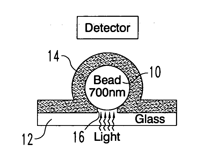
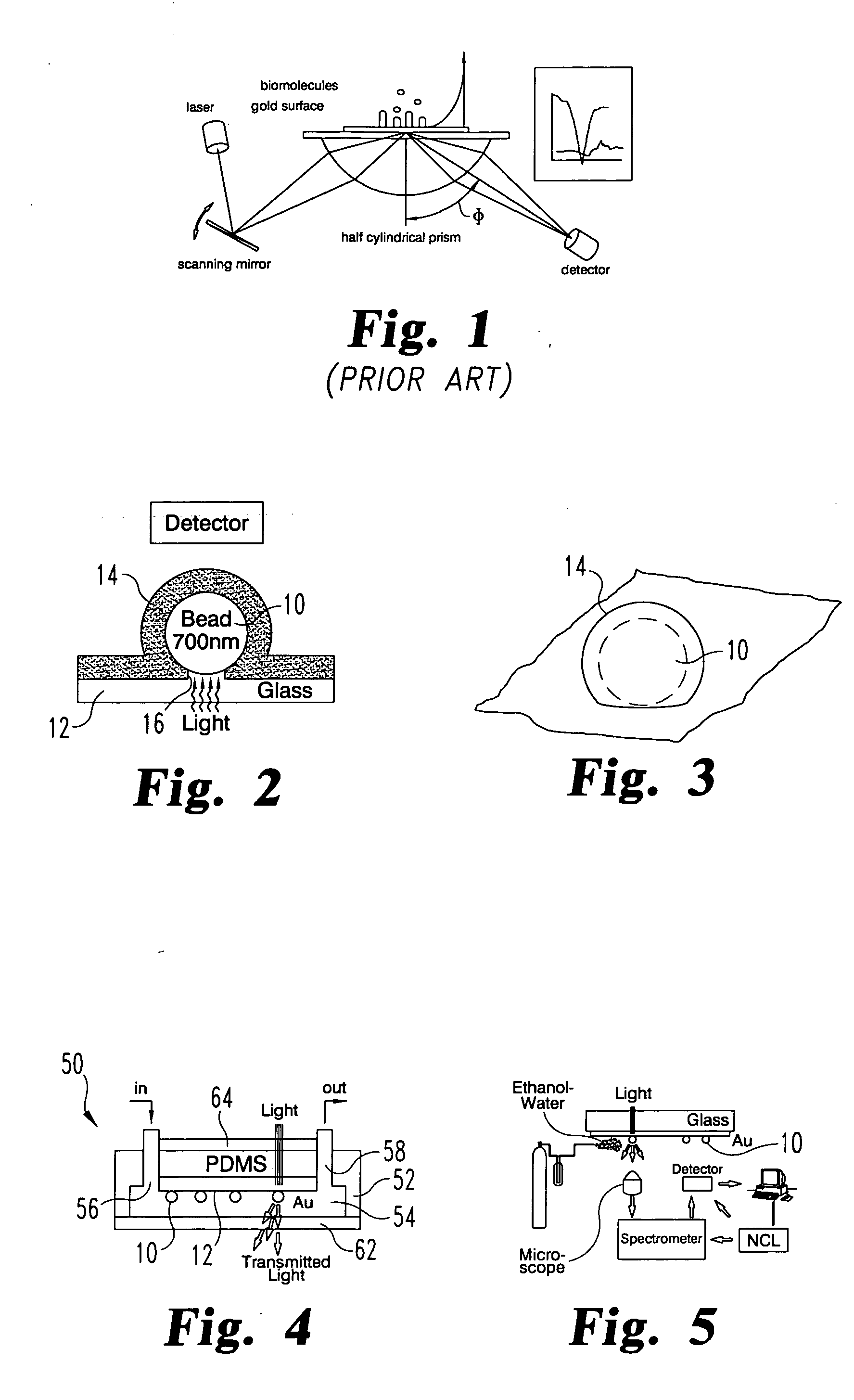
[0066] The following is a description of one method for laboratory fabrication of the MSPR sensor shown in FIG. 2. It is understood that other fabrication techniques are possible for specific applications. It is further understood that the immediately following description is principally for a sensor adapted for research use, rather than for commercial application, although the same principles may be applied to produce a commercially viable sensor.

[0067] Microscope cover glasses No. 1, 30×24 mm, 156 μm thick, are scored with a diamond and broken into four equal pieces. Also, microscope slides, 25 mm×75 mm are scored and broken into two equal pieces. The slides and cover glasses (items 12, 62 and 64, respectively, in FIGS. 2 and 4) are cleaned using a modified version of the well-known RCA cleaning protocol (H2O2: H2O: NH4OH-2:1:2, warmed to 70° C.) followed by rinsing in Di water and drying with N2. The cleaned cover glasses are placed in a dry a...

example 2

Fabrication of a Micro-fluidics Chip with MSPR Sensors

[0069] According to another embodiment of the invention, a process is provided for the fabrication of the sensors of the present invention in a micro-fluidic chip, such as the chip 50 shown in FIG. 4. Variations of the same protocol will allow fabrication of more complex sensors. In this process, the MSPR sensors are mounted within a housing, which in the preferred embodiments is in the form of a micro-chip. The micro-chip format for the MSPR sensor allows the sensor to be readily integrated into micro-systems, such as a micro-fluidics chip described herein.

[0070] In accordance with this embodiment, the fluidics chip is made using photolithographic technology and chip replica molding in polydimethylsiloxane (PDMS). The fluidics devices are fabricated using the negative-tone photoresist SU-8 as a master to cast PDMS channel structures. The master substrates are 50 mm×50 mm glass slides. The substrates are cleaned in HCI:HNO3 (3...

example 3

Operation of the Micro-fluidics MSPR Sensor Chip

[0075] In one method of using the micro-fluidics chip 50 (FIG. 4), fluid connections from the fluidics chip to fluid reservoirs, such as a syringe or a fluid pump, are made using 1.6 mm OD polypropylene tubing. The flows are controlled by adjusting the height of the reservoir connected to the input channel 56 relative to the height of the reservoirs connected to the output channel 58, or controlled by the fluid pump, so that a stable flow of about 1 μL / s is achieved. After the chip is connected to the reservoirs it is placed on a piezo-driven stage capable of motion in all three directions (3D) that can position the sensor chip in space with a precision of 10 nm. The whole ensemble is placed under an inverted microscope and microscope objectives of 40× and 60× are used to collect and analyze the signal coming from a single sensor.

[0076] The functionality and sensitivity of the MSPR sensor 50 may be evaluated using an experimental se...


PUM

PropertyMeasurementUnit
thickaaaaaaaaaa
incubation timeaaaaaaaaaa
thicknessaaaaaaaaaa

Abstract

A sensor for detecting the presence of a target analyte, ligand or molecule in a test fluid, comprises a light transmissive substrate, an array of surface plasmon resonant (SPR) elements mounted thereon, a light source arranged to direct light into the SPR elements, and a detector arranged to detect light transmitted through the SPR elements. The SPR elements may include a dielectric polystyrene sphere having a spherical diameter of about 770 nm with a gold coating layer about 150 nm thick. The interface between the SPR elements and the substrate forms a pinhole with a diameter less than the wavelength of the light directed into the elements to produce a near-field coupling mode within the micro-sized SPR elements. In specific embodiments, the pinhole diameter ranges between 150-200 nm. The SPR elements are contained within a molded PDMS chip that may incorporate micro-fluidic components, such as a pump and valves, to control flow of the test fluid across the SPR elements. A multi-channel sensor may be provided for detecting the presence of several targets with a single micro-chip sensor. In the multi-channel sensor collections of SPR elements are commonly functionalized to one of the several targets. The detectors sense changes in the resonant response of the SPR elements indicative of binding with the targets.

Description

CROSS-REFERENCE TO RELATED APPLICATION [0001] This application claims priority to co-pending provisional application No. 60 / 750,872, filed on Dec. 16, 2005, entitled “Sub-micron Cavity Surface Plasmon Sensors and Their Micro-fluidic Applications”, the entire disclosure of which is incorporated by reference herein.GOVERNMENTAL INTEREST [0002] Part of the work during the development of this invention was made with government support from the National Science Foundation under grant number IBM-0083653 and from NASA under grant number NAG2-1619. Pursuant to these grants, the U.S. Government has certain rights in the invention disclosed herein.BACKGROUND [0003] A significant trend in medicine is the introduction of point of care (POC) devices for rapid, bedside diagnosis. These devices enable rapid diagnosis by first responders or medical staff for time-critical diagnoses, such as for indicating whether patients are presenting with cardiac symptoms. Tests have been developed for other ind...

Claims


Application Information

Patent Timeline
Patent Type & Authority Applications(United States)
IPC IPC(8): G01N21/55
CPCB01L3/5027B82Y15/00B82Y30/00G01N2021/0346G01N21/553G01N21/554G01N33/54373G01N21/05G01N21/552G01N21/00
Inventor GLAZIER, JAMES A.DRAGNEA, BOGDANAMARIE, DRAGOS
Owner THE TRUSTEES OF INDIANA UNIV
Why Eureka
Try Eureka