Inspection instrument of a magnetic specimen

a magnetic specimen and instrument technology, applied in the direction of instruments, nuclear engineering, material analysis using wave/particle radiation, etc., can solve the problems of difficult no example in which the above spleem is applied to the evaluation of magnetic devices, etc., to achieve higher resolution, higher speed, and high speed

Inactive Publication Date: 2007-08-23
HITACHI LTD
View PDF16 Cites 14 Cited by
  • Summary
  • Abstract
  • Description
  • Claims
  • Application Information

AI Technical Summary

Benefits of technology

[0018]As described above, the SPLEEM system that has been obtained by the present invention is used, thereby making it possible to implement the inspection of the data and the servo signal which have been recorded on the magnetic disk at a higher speed and with a higher resolution.
[0019]However, the applied field of the present invention does not remain in the magnetic disk. The rotary stage is replaced with an XY stage that is actuated horizontally and vertically, and its intended use can be expanded to the general magnetic devices, for example, so as to inspect an MRAM produced on a wafer. Similarly, in this case, the obtained data is subjected to the Fourier transformation in the X-direction or the Y-direction, thereby making it possible to analyze the defective portion.
[0020]According to the present invention, there can be provided an inspection technique that is capable of inspecting the magnification state of various magnetic specimens at a higher speed and with a higher resolution.

Problems solved by technology

However, there is no example in which the above SPLEEM is applied to the evaluation of the magnetic device.
A specimen having a protection layer on a surface thereof and a specimen having an oxidized layer formed by exposure into the atmosphere once are not observed, and it is considered difficult to evaluate the magnetic device.

Method used


Image

  • Inspection instrument of a magnetic specimen
  • Inspection instrument of a magnetic specimen
  • Inspection instrument of a magnetic specimen

Examples


first embodiment

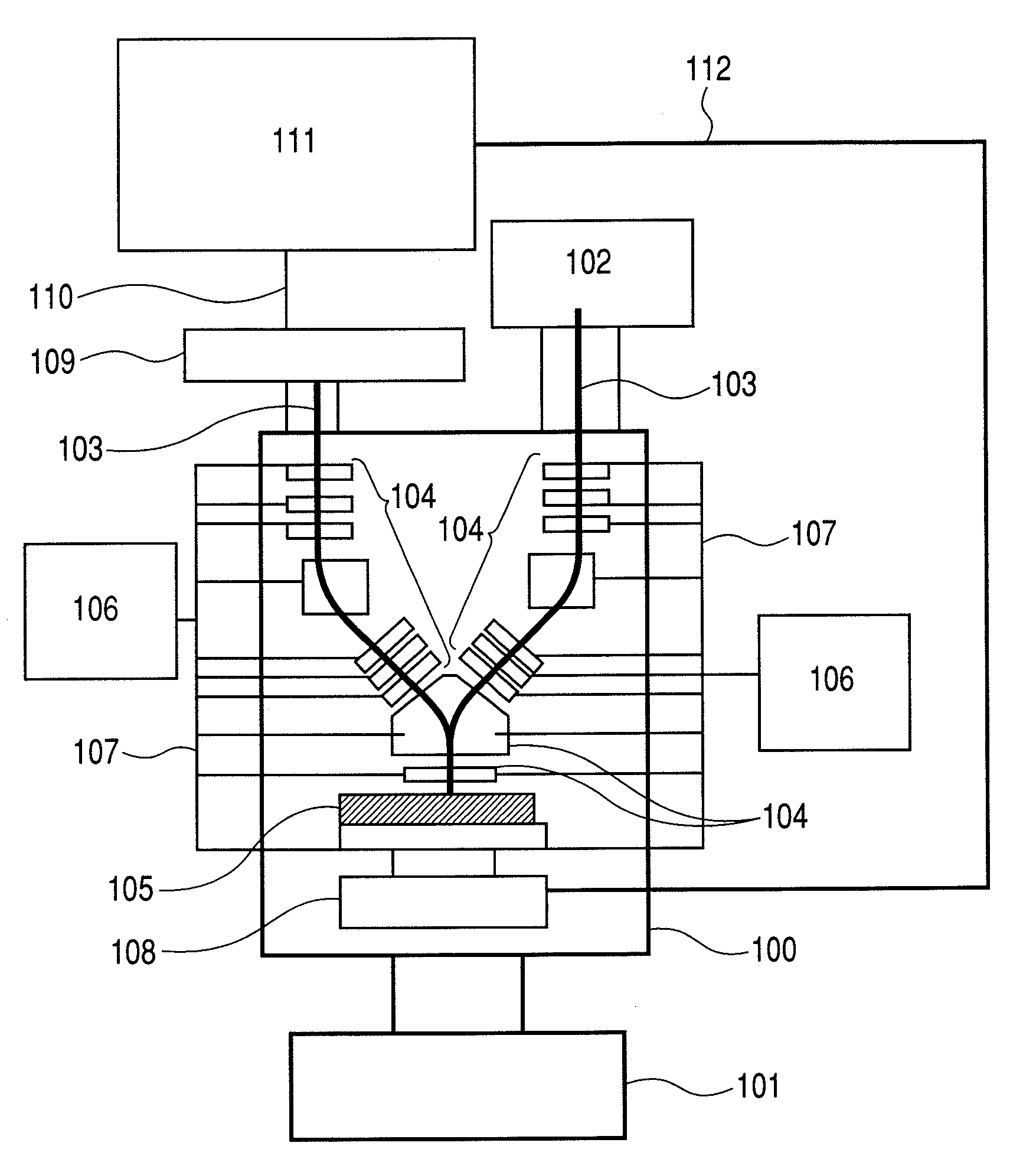
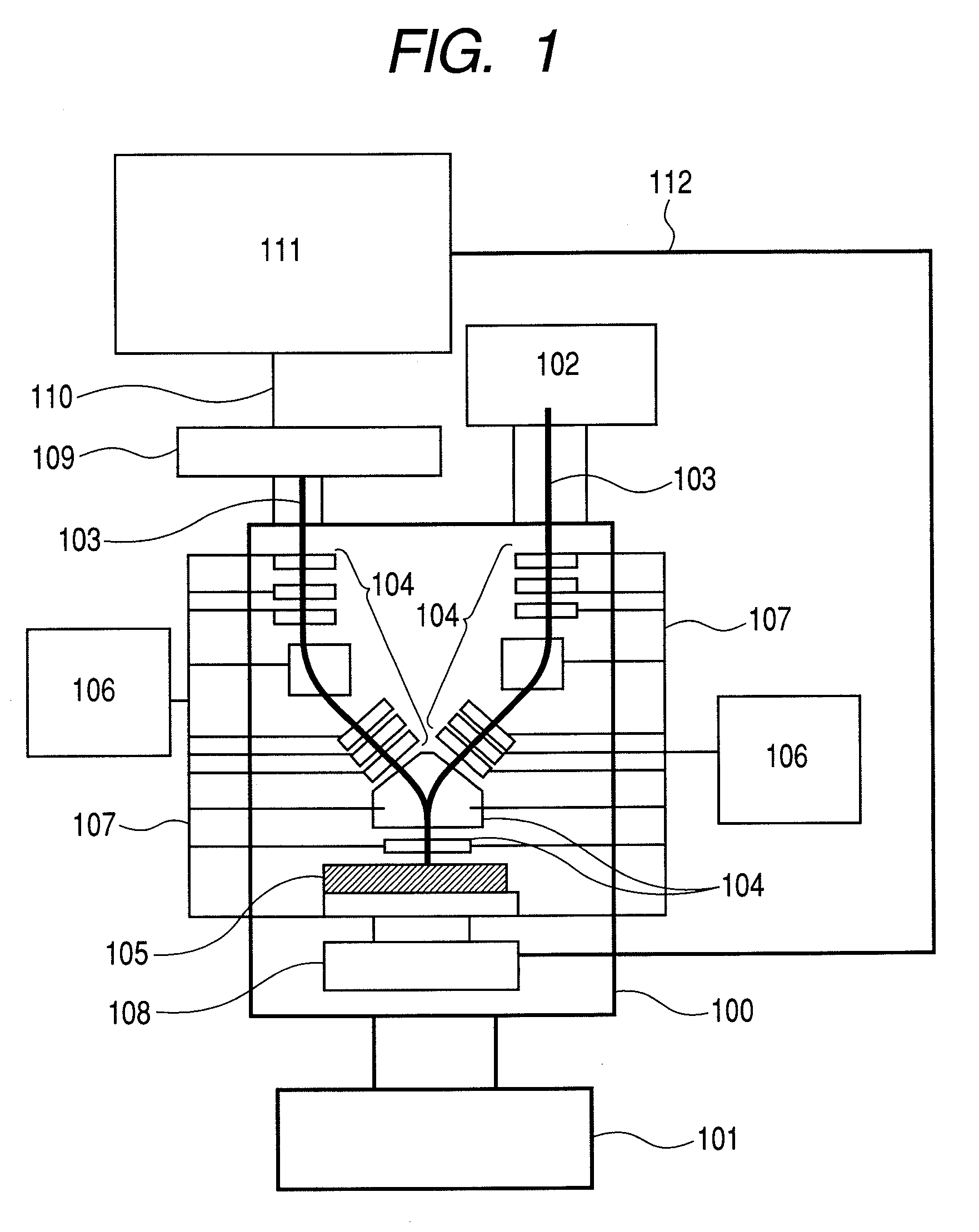
[0036]FIG. 1 is a diagram showing the outline configuration of an SPLEEM that is used in the present invention. In this example, a magnetic disk will be exemplified as a magnetic specimen.

[0037]In the SPLEEM measurement, because a sufficient signal is not taken unless the surface of a specimen is clean, the SPLEEM observation chamber 100 keeps an ultrahigh vacuum state so as not to contaminate the specimen surface, and an air is exhausted from the SPLEEM observation chamber 100 by means of, for example, an ion pump 101. The degree of vacuum of about 1×10⁻⁹ Torr is required. A spin polarized electron source 102 may provide a system in which a circular polarized light is projected to a semiconductor having an appropriate band gap such as GaAs to produce a spin polarized electron beam (reference document: Short-term research society for Physicality research “Physics developed by spin polarized electrons”, September 1993, Physicality Research “News from Physics Research”, Vol. 33, No. 3...

second embodiment

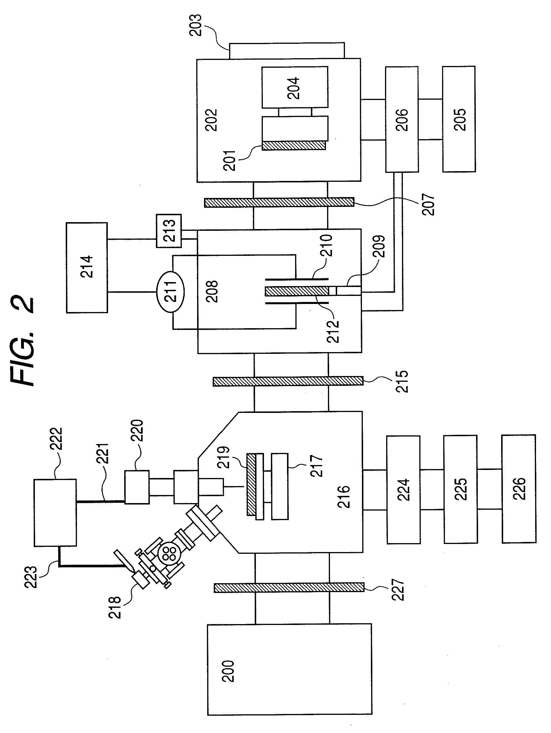
[0045]FIG. 3 shows another embodiment of the present invention. In this embodiment, the milling chamber 216 and the SPLEEM observation chamber 200 in FIG. 2 are integrated together, and a portion associated with the ashing process and the specimen introducing process other than the above integrated portion in FIG. 2 will be omitted. Also, the structure of the SPLEEM observation portion in FIG. 3 is basically identical with that in FIG. 1, and parts corresponding to reference numerals 300 to 311 in the figure have the same functions as those of reference numerals 100 to 111 in FIG. 1. In the figure, a transmission cable that connects the electron optics control unit of the focusing system and the high voltage cable, and a transmission cable that connects an image processing device 311 and a rotary stage 308 are omitted.

[0046]In other words, this embodiment is configured such that an ion gun 312 is installed in an SPLEEM observation chamber 300 within the same vacuum chamber. The ion ...

third embodiment

[0048]FIG. 4 shows still another embodiment of the present invention. Likewise, in this embodiment, a milling ion gun 412 is mounted in an SPLEEM observation chamber 400, and the SPLEEM observation can be performed in parallel with the milling. In the figure, the structure of the SPLEEM observation portion is basically identical with that in FIG. 3, and parts corresponding to reference numerals 400 to 417 in FIG. 4 have the same functions as those of reference numerals 300 to 317 in FIG. 3. A transmission cable that connects the electron optics control unit of the focusing system in the SPLEEM mechanism and a high voltage cable, and a transmission cable that connects an image processing device 411 and a rotary stage 408 are omitted.

[0049]The embodiment shown in FIG. 3 assumes the ashing process shown in FIG. 2 at a prestage, but this embodiment is so configured as to mill a specimen that has been brought from the atmosphere as it is. For that reason, a specimen introduction chamber ...


PUM


Abstract

An inspection technique capable of observing a magnetic domain configuration which is formed on a magnetic specimen surface with a higher resolution and at a higher speed as never before. The inspection technique includes an SPLEEM observation unit including a spin polarized electron source, an irradiation optics that projects a spin polarized electron beam that is emitted from the spin polarized electron source to a magnetic specimen having a magnetic domain structure, a stage on which the magnetic specimen is mounted, an imaging optics that focuses and detects the electron beam that is reflected from the magnetic specimen; and cleaning means for cleaning the surface of the magnetic specimen to transfer the magnetic specimen to the SPLEEM observation unit, wherein the magnetic domain structure of the magnetic specimen surface is inspected on the basis of the reflected electron beam.

Description

CLAIM OF PRIORITY[0001]The present application claims priority from Japanese application JP 2006-044875 filed on Feb. 22, 2006, the content of which is hereby incorporated by reference into this application.FIELD OF THE INVENTION[0002]The present invention relates to an inspection technology of a magnetic specimen such as a magnetic disk having a magnetic material on a surface thereof.BACKGROUND OF THE INVENTION[0003]A magnetic recording instrument is incorporated into a personal computer or a video cassette recorder, and the production volume of a magnetic disk or an optical disk which is a medium of the magnetic recording instrument tends to increase. Also, an MRAM (magnetic random access memory) has been actively developed as a next-generation semiconductor device.[0004]As the high density and the integration of the magnetic device such as the magnetic disk or the MRAM is more advanced, a magnetic domain size within the magnetic device is minimized with the result that it is impo...

Claims


Application Information

Patent Timeline
Patent Type & Authority Applications(United States)
IPC IPC(8): G21K7/00
CPCH01J37/29H01J2237/2067H01J2237/2538H01J2237/24564H01J2237/24557
Inventor KOHASHI, TERUOSHIMAKURA, TOMOKAZU
Owner HITACHI LTD
Why Eureka
Try Eureka