Micro Thermoelectric Type Gas Sensor

a gas sensor and micro-element technology, applied in the field of micro-element structure thermoelectric gas sensor, can solve the problems of difficult miniaturization of sensor elements, high power consumption of several watts, sensor has a poor response of several minutes to temperature increase, etc., and achieves low power consumption, high sensitivity, and low power consumption

Inactive Publication Date: 2007-09-13
NAT INST OF ADVANCED IND SCI & TECH
View PDF4 Cites 32 Cited by
  • Summary
  • Abstract
  • Description
  • Claims
  • Application Information

AI Technical Summary

Benefits of technology

[0019] With the foregoing in view, the inventors have conducted a comprehensive study aimed at the development of a novel technology that can solve the above-described problems inherent to the conventional technology and produce a microelement structure of a thermoelectric gas sensor. The results obtained have demonstrated that a gas sensor element that has a low power consumption and a high-speed response and is suitable for concentration measurements with hig

Problems solved by technology

Such sensor elements are difficult to miniaturize.
Yet another problem is that because the entire ceramic substrate is heated, the sensor has a poor response of several minutes to temperature increase and a high power consumption of several watts.
With regard to semiconductor gas sensors using the microheater technology, a large number of reports are published, but materials for gas detection element sections, for example, oxide semiconductors such as SnOx additionally containing a noble metal are very difficult to produce with high reliability.
The problem arising when high-temperature firing is used to produce an oxide semiconductor for gas detection with good stability is that characteristics of microheater and micropatterned wiring are degraded.
However, in gas detection devices using the electric resistance variation, gases with a low concentration cannot be detected, unless the microheater temperature is maintained with a high accuracy to increase the detection accuracy.
Furthermore, because a bridge circuit incorporating a reference (corresponds to a comparative element or a compensation element) is used, the structure of the gas detection device becomes complex.
Moreover, when gas species of a combustible gas comprising a gas mixture of hydrogen, carbon monoxide, methane, and the like are differentiated, it is difficult to select only a specific gas from the gas mixture.
For this reason, sensor structures are provided for detecting selectively a number of gas types, the signals from those sensor structures have to be information processed, the configuration becomes complex, and the cost is high.
In the gas sensor of this type, a low-temperature section is formed on a substrate, rather than on a membrane, and the resultant problem is that the increase in temperature of the high-temperature section is not stable and the response rate is low.
Furthermore, with regard to a structure providing gas selectivity, individual combustible gases are difficult to distribute and determine quantitatively, because a spatial control of catalyst temperature in the structure is extremely difficult.
Moreover, the sensor of this type has a complex structure, and therefore it is difficult to manufacture it, and signal processing is so complex that requires a large number of peripheral circuits.
Thus, the conventional sensors have a large number of problems that have to be resolved in order to attain a low power consumption, high-sensitivity concentration measurements, and high responsiveness, and there is a strong demand f

Method used


Image

  • Micro Thermoelectric Type Gas Sensor
  • Micro Thermoelectric Type Gas Sensor
  • Micro Thermoelectric Type Gas Sensor

Examples


embodiment 1

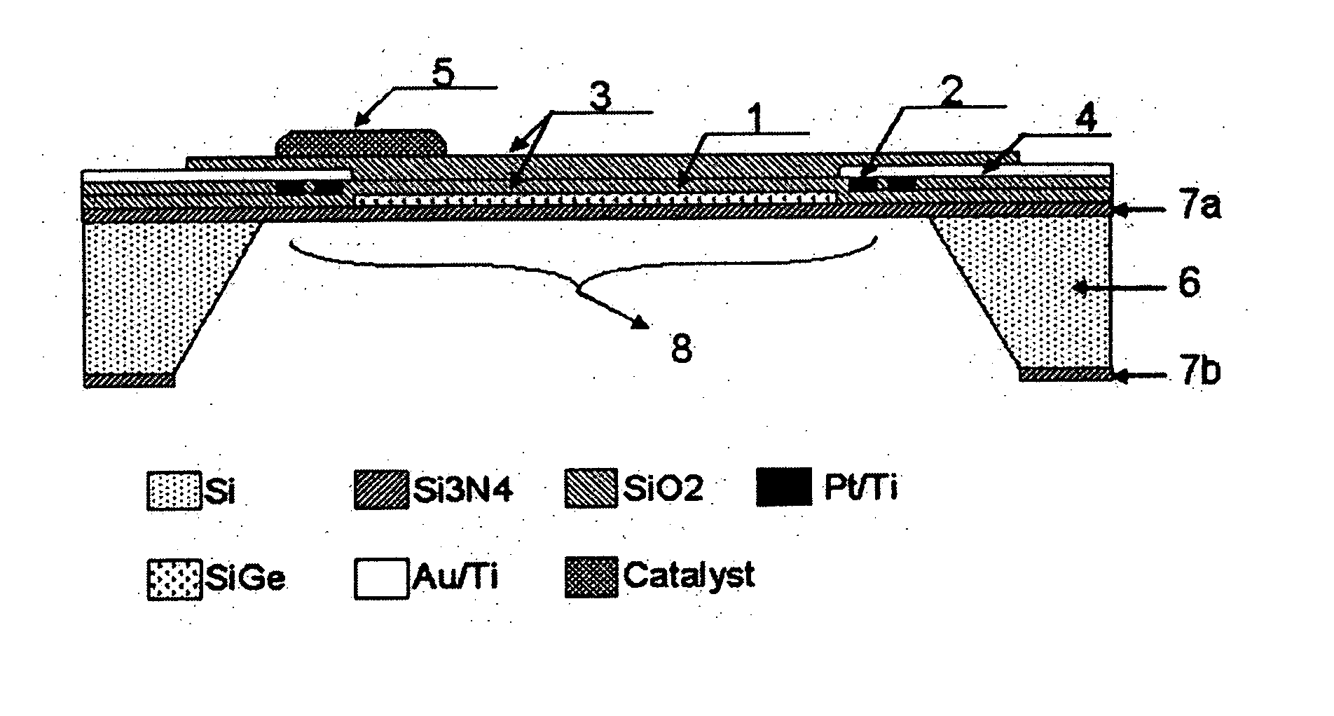
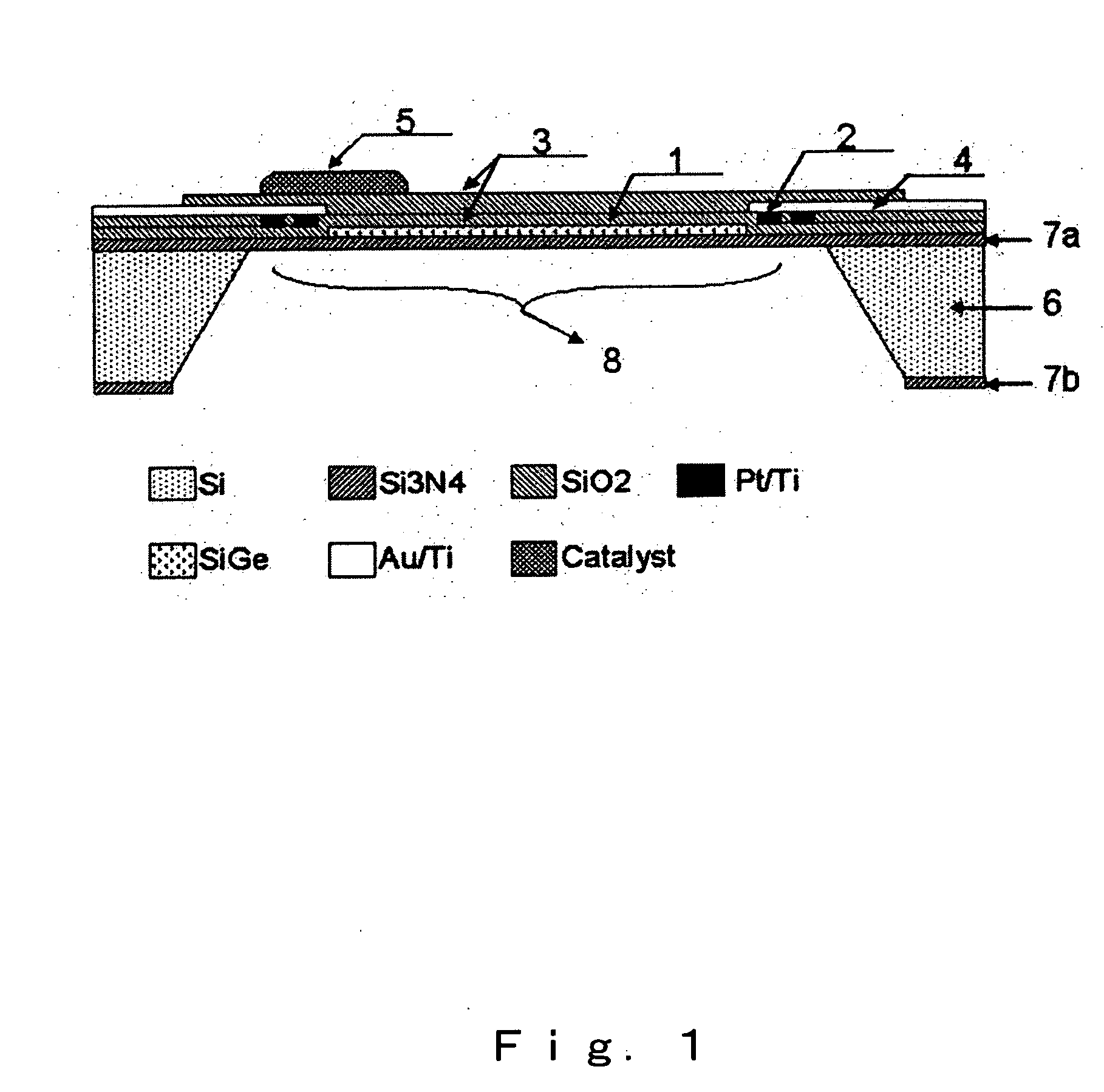
[0108] A specific feature of the micro thermoelectric sensor in accordance with the present invention that greatly differs in structure from the general micro gas sensors is that the microheater structure and thermoelectric thin film are formed at the same time. Because a membrane formed to provide for thermal shielding cracks easily from a level of 1 mm2, a large membrane is very difficult to produce. Accordingly, in the present embodiment, a micro thermoelectric hydrogen sensor was produced by fabricating a heater pattern, a thermoelectric pattern, and electrodes therefor within this surface area.

(1) Substrate

[0109] Because anisotropic etching of silicon is used in the fabrication of a microsensor, it is important to select appropriately the substrate and produce a film for etching stop. In the present embodiment, an oxide film and a nitride film were formed on a silicon substrate with a (100) plane and a thickness of about 300 μm. The oxide film was a thermal oxidation film gr...

embodiment 2

[0121] A gas response characteristic of the micro gas sensor was tested.

(1) Thermal Insulation by Membrane or Microheater

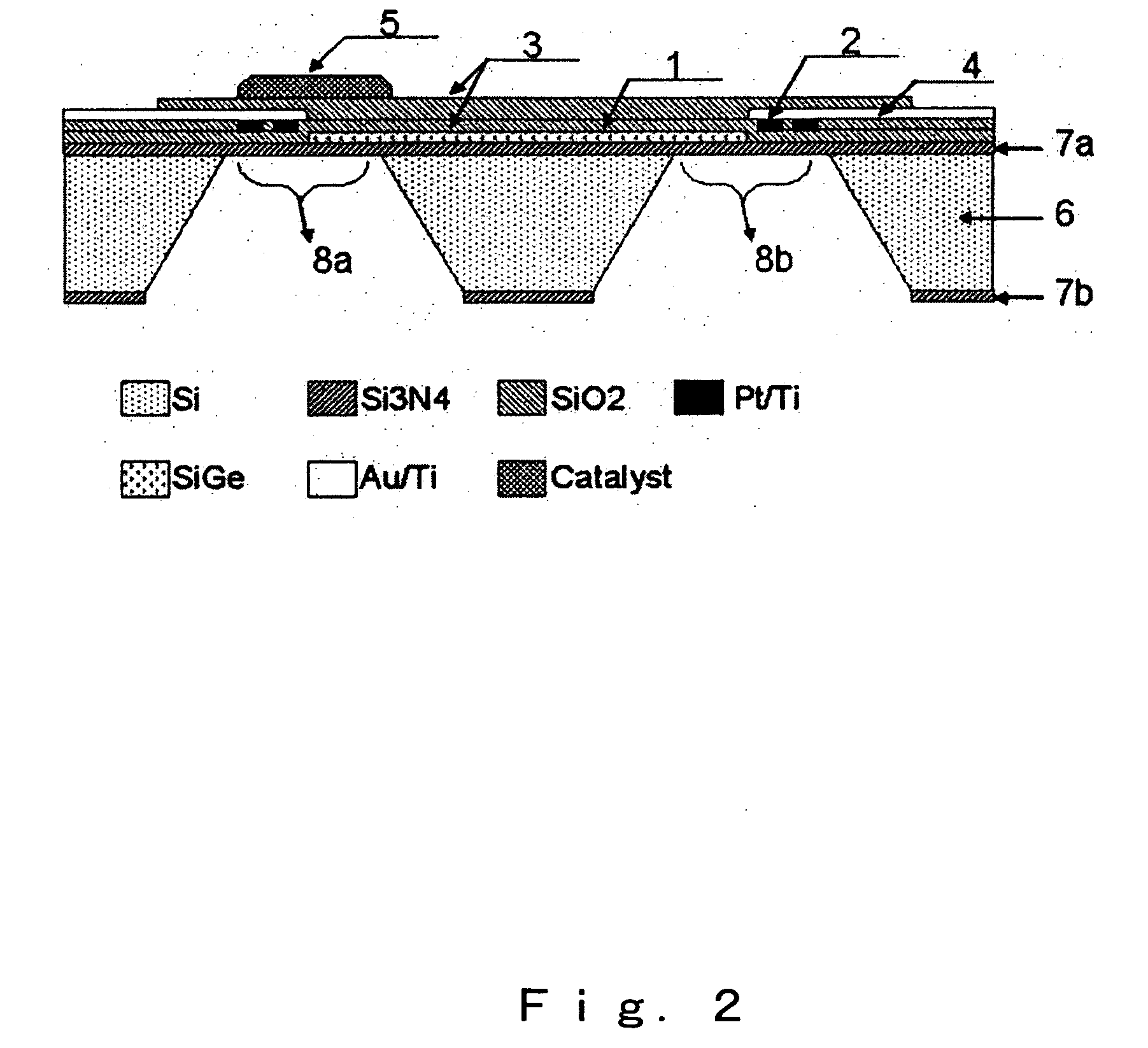
[0122]FIG. 5 shows a response characteristic to a 100 ccm flow of an air mixture gas containing 1% hydrogen when a microheater of a micro thermoelectric gas sensor was heated to 1001C. A generated voltage signal is plotted against the left axis, and the variations of temperature difference in a high-temperature portion and a low-temperature portion are plotted simultaneously against the right axis. By contrast when the film was formed on an alumina substrate, power consumption could be greatly reduced, and the consumed power was 50 mW at 100° C. for two membranes and 25 mW or less at 100° C. for one membrane element. Such low power consumption is due to excellent thermal insulation provided by the membrane structure and is a representative merit of the present microelement.

(2) Increase in Sensitivity

[0123] Owing to the thermal insulation effect, it was possi...

embodiment 3

[0128] In the present embodiment, pastes with various microstructures were produced and micropatterns of a catalyst were formed on a substrate by using a dispenser, as a preparatory test for finding a material for a paste to be used as a starting material for a functional material and for studying the relationship between the microstructure and the catalytic characteristic thereof.

(1) Preparation of Catalyst Powder and Paste Material

[0129] An aqueous solution of commercial platinum chloride and palladium chloride was prepared, immediately mixed with an oxide powder, and dried by heating to prepare a catalyst powder serving as a source starting material. The powder was mixed with a vehicle produced from terpineol and ethyl cellulose to prepare a paste-like functional material.

(2) Micropattern Formation with Dispenser

[0130] A catalyst was applied by using a dispenser to a predetermined position of an element and heated for 1 h at 300° C. to produce a catalyst. The catalyst was f...


PUM


Abstract

The present invention provides a micro thermoelectric gas sensor having a thermoelectric conversion section, a microheater, a catalyst layer formed on the microheater and to be heated by the microheater, which acts as a catalyst for catalytic combustion of a combustible gas, and a sensor detection section with an electrode pattern therefore formed on a membrane of a predetermined thickness, and a method for forming a micropattern of a functional material of a catalyst or resistor in a predetermined position on a substrate in a state in which the microstructure of the functional material remains controlled.

Description

TECHNICAL FIELD [0001] The present invention relates to a thermoelectric gas sensor having a microelement structure, and more particularly to an inexpensive micro gas sensor of a contact combustion type that has a simple configuration and can differentiate gas species in a combustible gas mixture with a high accuracy. The present invention provides a micro thermoelectric gas sensor of a novel type that has a low electric power consumption and enables highly sensitive concentration measurements and a high-speed response. [0002] The present invention also relates to a technology for forming three-dimensional micropatterns of functional materials, and more particularly to a method for forming a micropattern of a catalyst or resistor on a substrate of a gas sensor that detects the heat generated by a catalytic reaction of a combustible gas and a catalyst material as a detection signal, or on a substrate of a thermoelectric power generator that converts the heat into electricity, and als...

Claims


Application Information

Patent Timeline
IPC IPC(8): G01N27/16G01N25/32G01N33/00
CPCG01N27/16
Inventor SHIN, WOOSUCKIZU, NORIYAMATSUBARA, ICHIROMURAYAMA, NORIMITSUTAJIMA, KAZUKIQIU, FABINZHAO, ZHIHUI
Owner NAT INST OF ADVANCED IND SCI & TECH
Why Eureka
Try Eureka