Process for controlling the moisture concentration of a combustion flue gas

a technology of combustion flue gas and moisture concentration, which is applied in the direction of combustion types, separation processes, lighting and heating apparatus, etc., can solve the problems of increasing the cost of carbon dioxide capture, transportation and disposal technologies, and the ability to operate at significantly higher temperatures, so as to achieve the effect of convenient collection

Inactive Publication Date: 2007-10-18
THE BABCOCK & WILCOX CO
View PDF6 Cites 36 Cited by
  • Summary
  • Abstract
  • Description
  • Claims
  • Application Information

AI Technical Summary

Benefits of technology

[0014]In one aspect the present invention provides a new and unique method of reducing the moisture concentration of flue gas, the method comprising the steps of providing a flue gas comprised of combustion gases, passing the flue gas through a spray tower apparatus having a flue gas inlet and a flue gas outlet, providing a liquid reagent, storing the liquid reagent in a liquid reagent storage means, regulating the temperature of the liquid reagent in the liquid reagent storage means at a temperature below that of the flue gas water vapor dew point at the flue gas inlet, and cooling the flue gas by spraying the liquid reagent on the flue gas within the spray tower apparatus.
[0015]In another aspect, the present invention provides a new and unique method of combustion comprising combusting a fossil fuel in the presence of oxygen using a burner, creating a flue gas from the step of combusting, removing sulfur dioxide from the flue gas with a spray tower apparatus, reducing the moisture of the flue gas with the spray tower apparatus, and recirculating a portion of the flue gas exiting the scrubber apparatus to the burner to facilitate further combustion.
[0017]A spray tower according to the present invention operates in a non-adiabatic mode. In a wet scrubber embodiment of the present invention, the liquid reagent is cooled to a temperature below the dew point of the flue gas entering the wet scrubber. As the flue gas passes through the wet scrubber, the flue gas is sprayed with the cooled liquid reagent, causing the flue gas to cool and a portion of the moisture within the flue gas to condense. The condensate, generally water, falls to the bottom of the wet scrubber, providing the additional benefit of being readily collectable for use as make-up water for the liquid reagent solution.

Problems solved by technology

Current technologies proposed for capturing, transporting, and disposing of carbon dioxide from power generation facilities are energy intensive and expensive.
However, application of this technology to power generation facilities results in power losses exceeding 30% of plant output.
Yet, the substitution of oxygen for air can cause the combustion process to operate at significantly higher temperatures, sufficiently high in most case to cause irreparable damage to the furnace.
Additionally, in retrofit applications, the mass flow of flue gas would be only about one fifth as much as the boiler was designed, causing the heat transfer distribution to the various components of the boiler to change in ways detrimental to the generation of steam for the turbine generator.
For example for a typical high sulfur Illinois coal, the water vapor dew point temperature of flue gas can exceed 170 degrees Fahrenheit, making any recirculated flue gas unusable for coal drying in the pulverizer due to excessive moisture.
While effective, the physical size of this condensing heat exchanger necessary proved prohibitive, and raised other concerns such as but not limited to the production of an acidic condensate.

Method used


Image

  • Process for controlling the moisture concentration of a combustion flue gas
  • Process for controlling the moisture concentration of a combustion flue gas
  • Process for controlling the moisture concentration of a combustion flue gas

Examples


Embodiment Construction

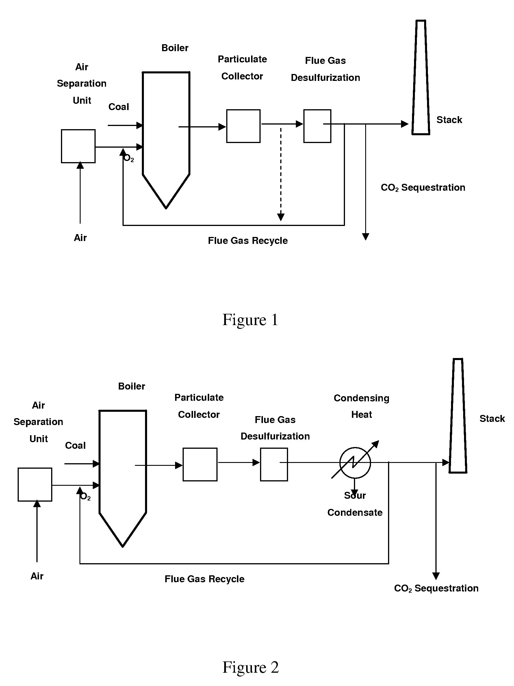
[0029]The present invention generally relates to a method of utilizing a spray tower to regulate the moisture concentration of a flue gas. In embodiments wherein spray towers such as wet scrubbers are used, the present invention provides for a method of duel purpose, wherein contaminants such as SO2 are removed in addition to the regulation of flue gas moisture concentration.

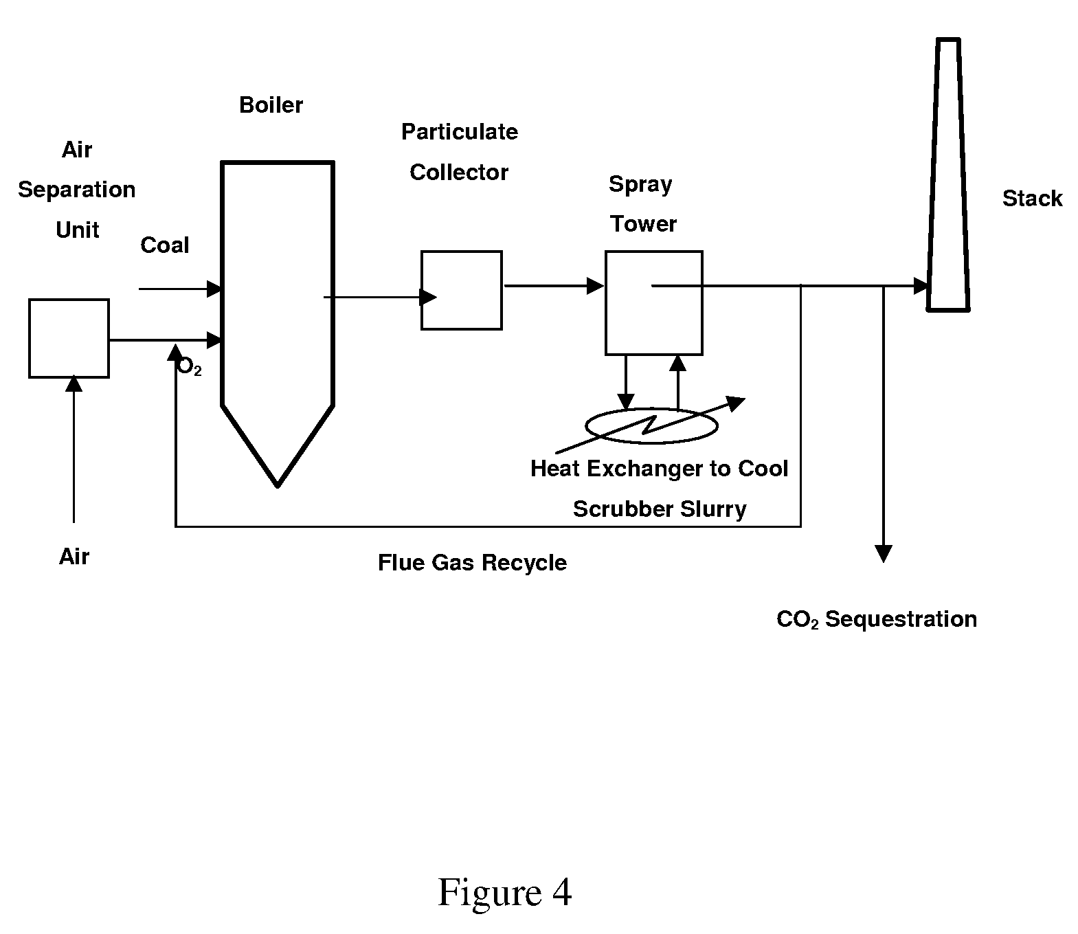
[0030]Referring to FIG. 4, a schematic representation of a combustion process according the present invention if shown. Oxygen and coal are supplied to a boiler upstream of a particulate collector and a flue gas desulfurization unit. The flue gas desulfurization unit is equipped with a heat exchanger to cool the liquid reagent. The liquid reagent is cooled to a predetermined point below that of the flue gas inlet temperature water vapor dew point and sprayed into the flue gas. A portion of the cooled flue gas is then reheated and recirculated to the pulverizer and burners to facilitate combustion. The recirculat...


PUM

PropertyMeasurementUnit
temperatureaaaaaaaaaa
adiabatic saturation temperatureaaaaaaaaaa

Abstract

The invention is related to a system for removal of moisture and contaminants from recirculated flue gas which is used for combustion in fossil fuel power plants. The system includes a spray tower having an inlet at one end of the housing and an outlet at an opposite end of the housing for channeling the flue gas into and out of the housing. Sprayers are located in the housing for spraying the flue gas with a liquid reagent to remove contaminants, including SO2, from the flue gas. A heat exchanger is integrally connected to the housing. The heat exchanger cools the liquid reagent before the reagent is sprayed onto the flue gas stream. The sprayers quench the flue gas stream with the cooled liquid reagent. The cooling of the liquid reagent to a temperature below the flue gas water vapor dew point improves the condensation of the water vapor in the flue gas during the spraying process. The flue gas exits the system with a lower moisture content and is redirected to burner for combustion. As a result, the efficiency the combustion process will improve with less moisture in the flue gas.

Description

FIELD AND BACKGROUND OF INVENTION[0001]The present invention relates generally to the removal of moisture and contaminants from flue gas, and in particular to a new and unique method of utilizing a spray tower to regulate the moisture content of a flue gas.[0002]Fossil fuel combustion is recognized as a major contributor to rising concentrations of carbon dioxide in the earth's atmosphere. The continually increasing carbon dioxide concentration has caused many governments and industries to examine the extensive use of fossil fuels and seek to develop new technologies for reducing carbon dioxide emissions. Major sources of carbon dioxide from fossil fuel utilization include coal-fired power plants, natural gas use for both power production and domestic heating and petroleum fuels for transportation. These three sources are believed to attribute to approximately 36%, 22% and 42%, respectively, of carbon dioxide emissions from fossil fuel fired combustion systems. As the use of coal at...

Claims


Application Information

Patent Timeline
Patent Type & Authority Applications(United States)
IPC IPC(8): B01D53/34
CPCB01D53/002B01D53/504B01D53/507B01D53/62Y02C10/04F23J15/003F23J2219/40F23J2219/70F23J2219/80F23C9/00Y02C20/40
Inventor DOWNS, WILLIAMDEVAULT, DOUGLAS J.MCDONALD, DENNIS K.FARZAN, HAMID
Owner THE BABCOCK & WILCOX CO
Why Eureka
Try Eureka