

Phosphor, Production Method Thereof and Light Emitting Instrument
a technology of phosphor and light emitting instruments, applied in the direction of solid-state devices, tubes with screens, gas discharge electrodes, etc., can solve the problems of unsuitable use in white leds, display, etc., and achieve the effects of reducing the number of lamps, and ensuring the effect of light intensity
- Summary
- Abstract
- Description
- Claims
- Application Information
AI Technical Summary
Benefits of technology
Problems solved by technology
Method used
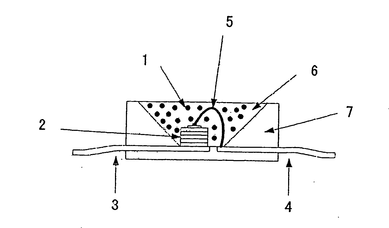
Image

Examples
example 1
[0154] Used as starting material powders were: a silicon nitride powder having an averaged particle size of 0.5 μm, an oxygen content of 0.93 wt %, and an α-type content of 92%; an aluminum nitride powder having a specific surface area of 3.3 m2 / g and an oxygen content of 0.79%; and a europium oxide powder having a purity of 99.9%.
[0155] To obtain a compound represented by a composition formula Eu0.002845Al0.463253Si0.02845N0.501185O0.004267 (Table 1 shows a designed composition, and a mixture composition of starting material powders), there were weighed 6.389 wt %, 91.206 wt %, and 2.405 wt % of a silicon nitride powder, an aluminum nitride powder, and a europium oxide powder; the powders were then mutually mixed for two hours by a wet-type ball mill adopting a pot made of silicon nitride sintered body, balls made of silicon nitride sintered bodies, and n-hexane. The n-hexane was removed by a rotary evaporator, to obtain a dried substance of the mixed powders. The obtained mixture...
examples 2 to 16
[0161] To obtain each composition shown in Table 1 by adopting the same starting material powders as Example 1, there were weighed predetermined amounts of a silicon nitride powder, an aluminum nitride powder, and a europium oxide powder; the powders were then mutually mixed for two hours by a wet-type ball mill adopting a pot made of silicon nitride sintered body, balls made of silicon nitride sintered bodies, and n-hexane. The n-hexane was removed by a rotary evaporator, to obtain a dried substance of the mixed powders. The obtained mixture was pulverized by an agate mortar and an agate pestle, followed by passage through a sieve of 500 μm, to obtain powder aggregations excellent in flowability. The powder aggregations were naturally dropped and loaded into a crucible made of boron nitride having dimensions of 20 mm diameter and 20 mm height. Next, the crucible was set into an electric furnace of black lead resistance heating type. There was conducted a firing operation by firstly...
examples 17 to 61
[0162] Used as starting materials were the same silicon nitride powder and the same aluminum nitride powder as Example 1, and powders of boron oxide, boron nitride, manganese carbonate, cerium oxide, praseodymium oxide, neodymium oxide, samarium oxide, europium oxide, terbium oxide, and dysprosium oxide. To obtain each composition shown in Table 3, there were weighed predetermined amounts of starting material powders shown in Table 4, and the powders were then mutually mixed for ten minutes by a mortar and a pestle both made of silicon nitride. The obtained d mixture was passed through a sieve of 500 μm, to obtain powder aggregations excellent in flowability. The powder aggregations were naturally dropped and loaded into a crucible made of boron nitride having dimensions of 20 mm diameter and 20 mm height. Next, the crucible was set into an electric furnace of black lead resistance heating type. There was conducted a firing operation by firstly bringing the firing environment to vac...
PUM
| Property | Measurement | Unit |
|---|---|---|
| emission peak wavelength | aaaaa | aaaaa |
| emission peak wavelength | aaaaa | aaaaa |
| emission peak wavelength | aaaaa | aaaaa |
Abstract
Description
Claims
Application Information