Electrical Charge Storage Device Having Enhanced Power Characteristics

a technology of electric charge storage and power characteristics, which is applied in the direction of capacitor dielectric layers, instruments, cell components, etc., can solve the problems of limiting the utility of conventional capacitor selection, limiting the operation utility of capacitors in dc applications, and wide-spread implementation of series capacitors, so as to increase the total charge density of capacitors, enhance the charge accumulation rate of capacitors, and increase instantaneous current capability of capacitors

Inactive Publication Date: 2007-12-13
DUFF WILLIAM B JR
View PDF25 Cites 18 Cited by
  • Summary
  • Abstract
  • Description
  • Claims
  • Application Information

AI Technical Summary

Benefits of technology

[0032] As used herein, the term “conformal coating” shall mean without limitation the touching and / or bonding of one layer to another. The shapes of the two layers at their interface or boundary shall be matched as closely as practicable. If layer ‘A’ is concave in a region, then layer ‘B’ must be convex in this region to achieve this effect. The convex layer ‘B’ must be smaller than the concave layer ‘A’ in order to achieve this effect. In general, the tighter the fit of the conformal coating, the greater the bond strength and conformance of the conformal coating; and this provides a superiority of the boundary characteristics. Preferably, uniformity of conformal coating thickness is desirable.
[0252] In one implementation of the electrical charge storage device, the charge accumulation rate of the capacitor is enhanced by the use of sharpy structures.

Problems solved by technology

While these and many other series capacitor advantages are well known, unit cost, size requirements, voltage limitations, current limitations, dv / dt limitations, di / dt limitations, insulation limitations, dielectric limitations, electromechanical limitations and thermodynamic limitations, have prevented widespread implementation of series capacitors, especially in low frequency applications.
However, low ratios of instantaneous and steady state power capability to total stored energy tend to limit the operating utility of capacitors in DC applications.
High ESR and overheating often limit the utility of conventional capacitor selections such as electrolytic capacitance in DC and signal coupling applications.
Unfortunately, non-polarized capacitors—especially in series configurations—are not well-suited for many AC and DC applications due to limitations in size, capacitance, weight, efficiency, energy density, and cost.
Singular polarized capacitors traditionally have been limited to use in DC and small AC signal coupling applications due to their unidirectional, forward biasing requirements.
The rated voltage of such capacitors is limited by the dielectric constant, dielectric strength, and material and fabrication defects.
The failure mechanism of shorting and then burn through can be disruptive in sensitive circuits such as digital devices.
Further, metalized film capacitors tend to poorly dissipate heat.
This creates internal hot spots and tends to accelerate capacitor failure.
In such implementations, dielectric breakdown and failure of such capacitor embodiments often are associated with concentrations of charge accumulations at corners and sharp points of the conductive plates and material defects and variation of thickness in high electric field conditions.
Although the capacitor can be designed and the dielectric material chosen such that the capacitor theoretically should withstand such conditions, conventional macroscopic manufacturing methods often do not provide the accuracy and control needed to ensure that the fabricated capacitor can perform at its theoretical capability.
For example, conventional techniques cannot ensure that sharp corners or burrs on the conductors will be avoided, or that the thickness of the dielectric material will be uniform throughout its area, or that the dielectric will be disposed on the conductors in a conformal manner.
Further the surface area of parallel-plate-type capacitors has been generally limited to flat place construction and conventional enhancement techniques such as plate sharing and spiral wound packaging.
Polarized capacitors have enhanced surface area as compared to non-polarized capacitors, which, unfortunately, introduces additional capacitor components, a charge transport mechanism, and additional losses.
Despite these advantageous properties, polarized capacitors also have their drawbacks.
The electrically directional capacitance versus rectification circuit behavior due to electron tunneling is often disadvantageous.
Further, electrolytic capacitors outgas hydrogen due to the electrolysis of water, and ion transport limitations and conductor termination practices tend to contribute to a steep frequency response curve.
Still further, the maximum AC ripple current that can be tolerated by electrolytic capacitors is limited by the ESR, rated voltage and the thermodynamic, mechanical, and venting properties of the capacitor package that allow it withstand the resultant heat and pressure buildup without rupturing.
Further, the most commonly used material, aluminum, requires great energy to refine conventionally.
Other conventionally constructed polarized charge storage devices suffer innumerable similar disadvantages.
These methods, though somewhat effective tend to increase costs substantially and in many cases substantially increase the physical size and weight of the components.
Typically, for both polarized and non-polarized discrete capacitors, neither the theoretical dielectric strength nor the theoretical dielectric constant, have been effectively realized due to material imperfections, imprecise manufacturing processes, and boundary interface problems.
These factors, in turn, limit both the maximum rated device voltage and capacitance that may be attained for a given capacitor implementation.
Still further, imbalances in conduction current and displacement current capabilities combined with inconsistent material properties limit the transient and sustained current capabilities for a given capacitor.
Structural thermodynamic limitations further tend to limit transient and steady state electrical current capabilities and capacitor operational lifetime.
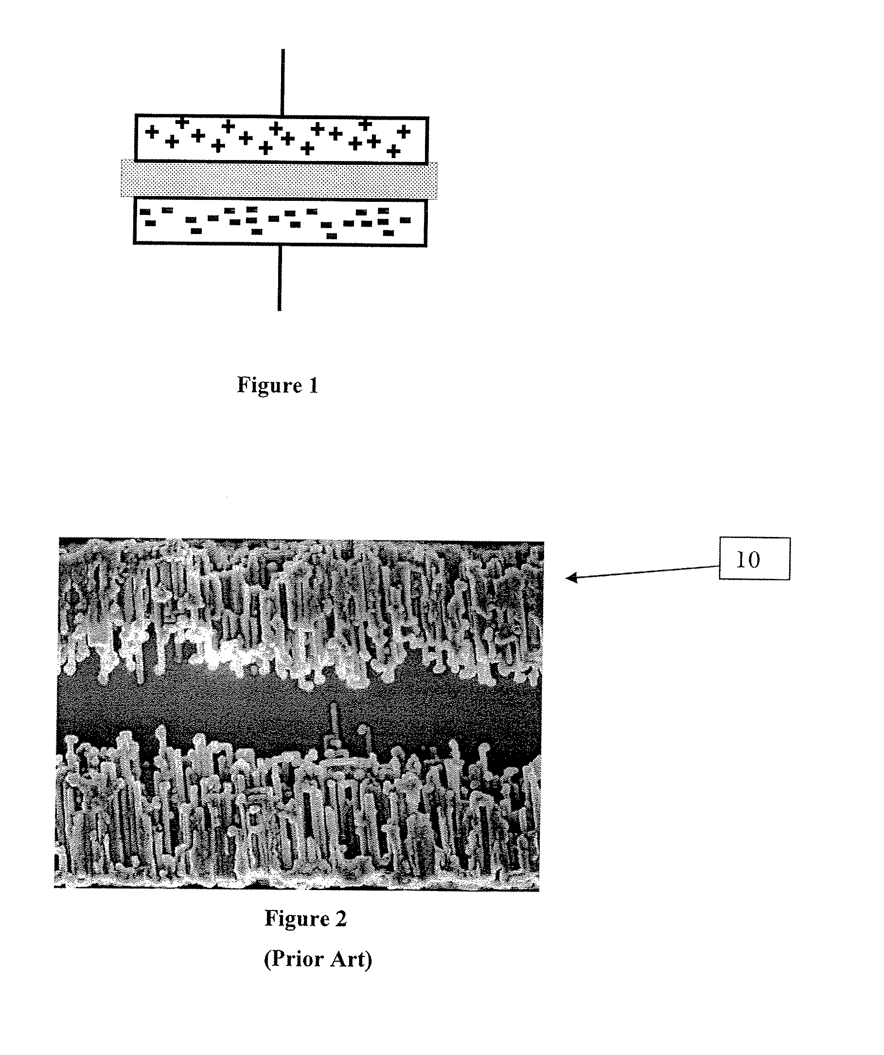
However, it is difficult to charge the capacitor, particularly at high voltages due to spatial distance variations between the extremities of the broom-straw-like structures and the attendant displacement current limitations.
The configuration illustrated in FIG. 2 has many characteristics which ultimately limit the performance and longevity of the capacitor.
Mechanical weakness of the structure and required anodization thickness limit capacitor rated voltage.
Another drawback to aluminum electrolytic capacitors is the enormous quantity of energy required for fabrication.
Great amounts of electrical power are required for heating, oxidizing and forming the aluminum foil and tab materials.
These steps and inputs are highly energy intensive.
Thus, conventional manufacturing techniques for aluminum electrolytic capacitors require a substantial quantity of energy.
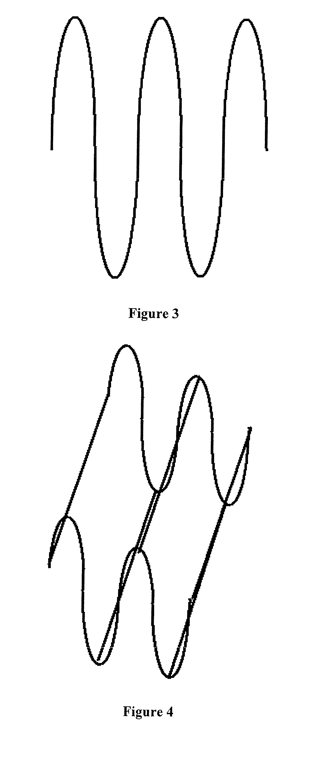
This operating condition alternates every half cycle and greatly shortens capacitor assembly life and is a source of electrical harmonic current and ground reference voltage disturbances.
Printed circuit board electrical, thermal and mechanical limitations severely limit integrated capacitor materials and construction techniques.
Also integrated capacitance variation cannot be easily controlled using conventional manufacturing techniques.
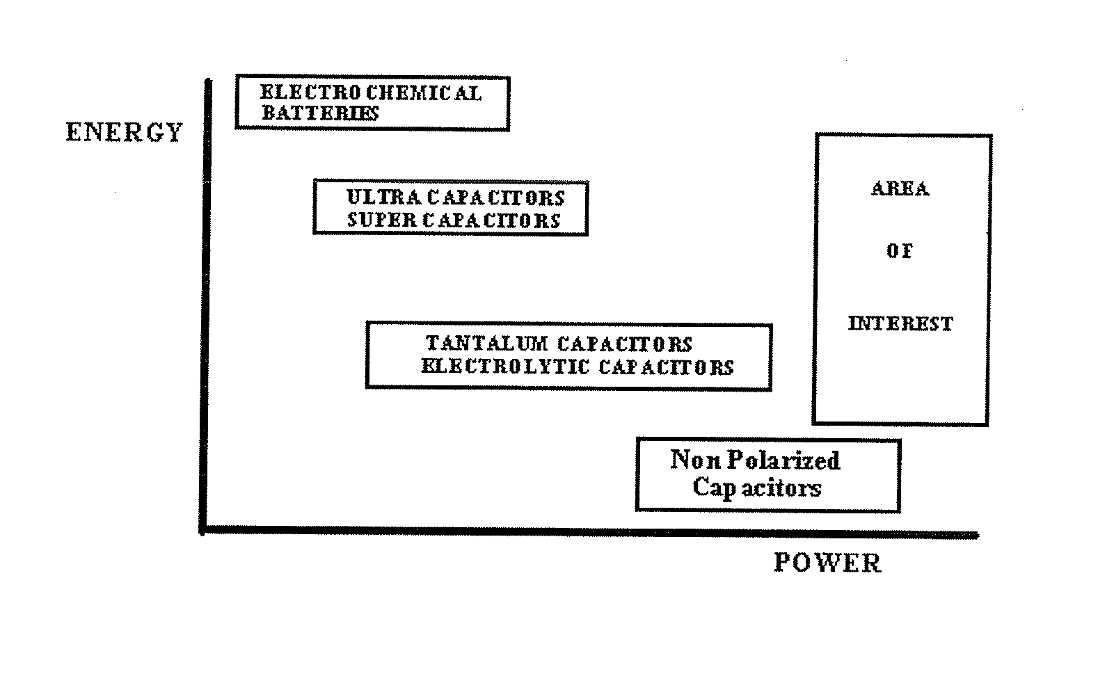
Super capacitors, ultra capacitors and double layer capacitors, however, have many limiting characteristics which inhibit their usefulness for power applications.
Further, the devices are polarized charge storage devices, thus restricting their usefulness in AC power applications.
Further, such devices often fail to deliver the full charge stored on demand.
A great deal of the stored charge can remain unavailable.
Not all the stored energy which can be put to use, can be released instantaneously, making the devices less suitable for rapid rate charge and discharge applications.
More particularly, electrical motors presently consume about 65% of metered real power.

Method used


Image

  • Electrical Charge Storage Device Having Enhanced Power Characteristics
  • Electrical Charge Storage Device Having Enhanced Power Characteristics
  • Electrical Charge Storage Device Having Enhanced Power Characteristics

Examples


Embodiment Construction

[0274] Capacitors are generally described mathematically by those knowledgeable in the field. There are several systems of units and conversions which are commonly employed. It is not uncommon to jump back and forth among systems. The basic physical and mathematical definitions and relationships are as follows, using the passive sign circuit convention, where applicable:

Q = 8.9874 × 10⁹ Nm2Cou2(Unit of Charge, the Coulomb)E0 = 8.854 × 10¹² Cou2 / NM2(Permittivity of Free Space)C = Q / Vv = (1 / C) Σidt + vt0(Summation or Integral from t0 until tf)i = C dv / dtp = vi = Cv dv / dtw = Cv2 / 2C = E0 ER (A / d)(Parallel Plate Capacitor Geometry)

[0275] Capacitors are characterized by certain qualitative circuit actions and reactions. This circuit behavior is summarized by the following heuristics: i) capacitors will permit an instantaneous change in terminal current, ii) capacitors will oppose an instantaneous change in terminal voltage, and iii) charged capacitors appear as an open circuit to consta...


PUM

PropertyMeasurementUnit
relative dielectric constant ERaaaaaaaaaa
distanceaaaaaaaaaa
conductiveaaaaaaaaaa

Abstract

The present invention relates generally to an electrical charge storage device (ECSD) with enhanced power characteristics. More particularly, the present invention relates to enhancing the current density, voltage rating, power transfer characteristics, frequency response and charge storage density of various devices, such as capacitors, batteries, fuel cells and other electrical charge storage devices. For example, one aspect of the present invention is solid state and electrolytic capacitors where the conductor surface area is increased with smooth structures, thereby reducing the distance separating the conductors, and improving the effective dielectric characteristics by employing construction techniques on atomic, molecular, and macroscopic levels.

Description

RELATED APPLICATIONS [0001] This Application is a Divisional of U.S. patent application Ser. No. 10 / 793,638, filed Mar. 4, 2004, which claims priority to U.S. Provisional Patent Application No. 60 / 452,266, filed Mar. 5, 2003.TECHNICAL FIELD [0002] The present invention relates generally to an electrical charge storage device (ECSD) with enhanced power characteristics. More particularly, the present invention relates to enhancing the current density, voltage rating, power transfer characteristics, frequency response and charge storage density of various devices, such as capacitors, batteries, fuel cells and other electrical charge storage devices. For example, one aspect of the present invention is solid state and electrolytic capacitors where the conductor surface area is increased with smooth structures, thereby reducing the distance separating the conductors, and improving the effective dielectric characteristics by employing construction techniques on atomic, molecular, and macro...

Claims


Application Information

Patent Timeline
Patent Type & Authority Applications(United States)
IPC IPC(8): H01G9/155H01G9/004G03G5/02G11B7/249H01M4/58G11B7/257H01G4/005H01G4/01H01G4/012H01G9/04H01G9/048H01L27/08H01M4/66H01M4/78H01M8/02
CPCG03G5/0202Y02E60/50G11B7/2532G11B7/2572G11B7/2578G11B2007/25706G11B2007/25708G11B2007/25715H01G4/005H01G4/01H01G4/012H01G9/04H01G9/048H01L27/0805H01M4/66H01M4/667H01M4/78H01M8/0245H01M8/0247G11B7/249Y10T428/249986Y02E60/10H01G4/06H01G5/013H01G9/07
Inventor DUFF, WILLIAM B. JR.
Owner DUFF WILLIAM B JR
Why Eureka
Try Eureka