Medical Filter Material, and Extracorporeal Circulation Column and Blood Filter Utilizing the Filter Material

a filter material and nanofiber technology, applied in the direction of filtration separation, other blood circulation devices, separation processes, etc., can solve the problems of low absolute strength of fibers, inability to improve the productivity of filter materials, and inability to carry out leukocyte removal uniformly in local parts of filter materials, etc., to achieve excellent hemadsorption performance, high productivity, and high strength

Inactive Publication Date: 2008-01-31
TORAY IND INC
View PDF6 Cites 20 Cited by
  • Summary
  • Abstract
  • Description
  • Claims
  • Application Information

AI Technical Summary

Benefits of technology

[0014] In the medical filter material according to the present invention, because nanofibers small in dispersion of fiber diameter, high in strength and high in productivity are used, a medical filter material excellent in hemadsorption performance and protein adsorption performance can be realized. By packing this medical filter material, high-performance medical equipment and materials, particularly, an extracorporeal circulation column and a blood filter can be provided.
[0015]FIG. 1 is a diagram showing a result of observing a cross section of nanofibers in the present invention by TEM.
[0016]FIG. 2 is a diagram showing a resul

Problems solved by technology

Indeed, the leukocyte removal filter material described in Patent document 1 is excellent in ability for removing leukocytes, but, because it uses cellulose fibril and there occurs a dispersion in the diameter of cellulose fibers in the fibrillation, there is a fear that the leukocyte removal is not carried out uniformly in a local part of the filter material.
Further, although a method for making acetic bacteria produce cellulose fibers having a diameter of several tens nanometer order is also proposed in Patent document 1 in order to unify the fiber diameter, the absolute strength of the fiber is low because the fiber is too thin, there are a problem that it becomes necessary to increase the pressure resistance for treating a large amount of blood, and a problem that the productivity of the filter material cannot be improved because it takes a long time to produce cellulose by aceti

Method used


Image

  • Medical Filter Material, and Extracorporeal Circulation Column and Blood Filter Utilizing the Filter Material
  • Medical Filter Material, and Extracorporeal Circulation Column and Blood Filter Utilizing the Filter Material
  • Medical Filter Material, and Extracorporeal Circulation Column and Blood Filter Utilizing the Filter Material

Examples


example 1

[0128] N6 [nylon 6] (20% by weight) with a melt viscosity of 53 Pa·s (at 262° C., shear speed: 121.6 sec−1) and a melting point of 220° C. and PET [polyethylene terephthalate] copolymerized with 8 mol % isophthalic acid and 4 mol % bisphenol A with a melt viscosity of 310 Pa·s (at 262° C., shear speed: 121.6 sec−1) and a melting point of 225° C. (80% by weight) were kneaded at 260° C. by a twin-screw extruding kneader to prepare polymer alloy chips. Where, the melt viscosity at 262° C. and 121.6 sec−1 of this copolymerized PET obtained was 180 Pa·s. The kneading condition at that time was as follows. As to polymer supply, N6 and the copolymerized PET were metered separately, and supplied to the kneader separately. A screw with a diameter of 37 mm, an effective length of 1670 mm and L / D (ratio of screw part length / diameter) of 45.1 was used. A model diagram of a melt spinning apparatus used for the melt spinning is shown in FIG. 5. In FIG. 5, label 6 indicates a hopper, label 7 indic...

example 3

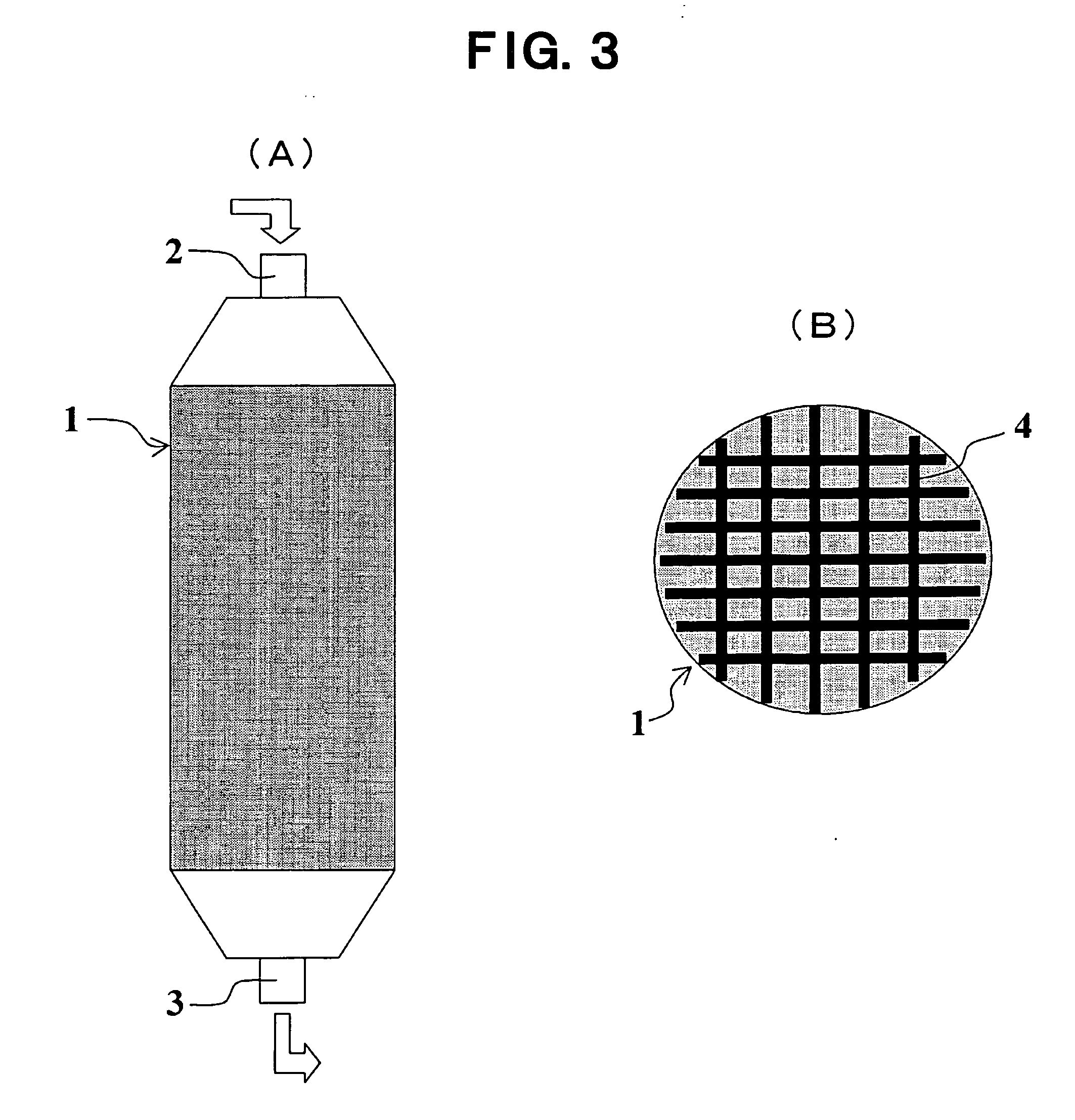
[0139] The filter material obtained in Example 1 was packed into a cylindrical PP (polypropylene) vessel with a diameter of 4.7 cm and a length of 17 cm at a lattice form, and an extracorporeal circulation column was made so as to form a body fluid flow parallel to the filter substrate. The schematic diagram of the lattice form was shown in FIG. 3(B). When a bovine blood was passed through this column at a flow rate of 2 mL / min. for 90 minutes, an extracorporeal circulation column having a sufficient liquid passage property without clogging could be obtained.

example 4

[0140] A PP (polypropylene) nonwoven fabric with a weight of 240 g / m2 was prepared by applying carding and wrapping to PP raw stock with a single fiber fineness of 1.9 dtex and further carrying out needle punching at a punch density of 500 / cm2. 5 g of the water dispersion of N6 nanofibers prepared in Example 1 and 20L of water were charged into a rectangular sheet machine, after made as a paper on the. PP nonwoven fabric, it was dried as it is at 110° C. using a high-temperature rotational type drier (produced by Kumagaya Riki Kogyo Corporation), thereby obtaining a medical filter material in which N6 nanofibers were dispersed on the PP nonwoven fabric in a net-like form. The weight of this medical filter material was 240 g / m2, and the apparent density thereof was 0.02 g / m3.

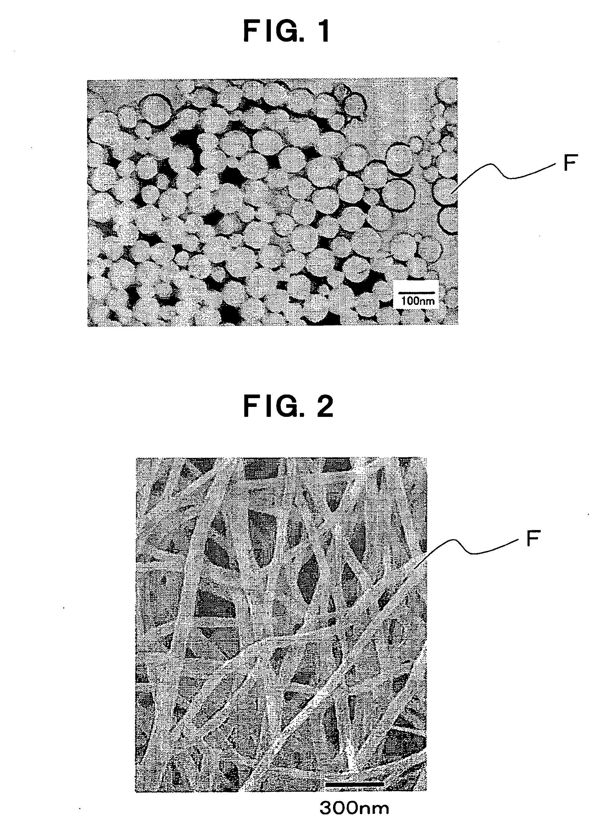
[0141] Only N6 nanofibers were taken out from the obtained filter material, and as the result of analyzing in the same manner as that in Example 1, the number average diameter of the nanofibers was 56 nm which w...


PUM

PropertyMeasurementUnit
Fractionaaaaaaaaaa
Diameteraaaaaaaaaa
Diameteraaaaaaaaaa

Abstract

A medical filter material characterized by comprising a dispersion of nanofibers of thermoplastic polymer having a number average diameter of 1 to 500 nm wherein the ratio of single fibers with a diameter of more than 500 nm and 1 μm or less is 3% or less in terms of weight ratio. Further, there are provided, utilizing the medical filter material, an extracorporeal circulation column and a blood filter. Through the employment of nanofibers small in fiber diameter dispersion, high in strength and high in productivity, there can be provided a medical filter material excellent in hemadsorption performance and protein adsorption performance. Through packing with this medical filter material, there can be provided high-performance extracorporeal circulation column and blood filter.

Description

TECHNICAL FIELD OF THE INVENTION [0001] The present invention relates to a medical filter material using nanofibers, and an extracorporeal circulation column and a blood filter utilizing the filter material. Where, the term of “nanofibers” in the present invention means single fibers having a number average diameter of the single fibers in a range of 1 nm or more and 1 μm or less. Further, this nanofiber may be in a fibrous form, and it is not limited in length, sectional shape and the like. More specifically, the present invention relates to a medical filter material using such nanofibers, and in particular, relates to a medical filter material using novel nanofibers which can develop the use in the medical field based on the fineness, that has not been achieved in the conventional technology, and the uniformity of the fineness, and an extracorporeal circulation column and a blood filter utilizing the filter material. BACKGROUND ART OF THE INVENTION [0002] In inflammatory diseases ...

Claims


Application Information

Patent Timeline
IPC IPC(8): B01D39/00A61M1/02A61M1/34A61M1/36B01D39/16
CPCA61M1/3679B01D2239/1291B01D39/1623B01D2239/0216B01D2239/0233B01D2239/025B01D2239/0421B01D2239/0478B01D2239/0609B01D2239/0613B01D2239/0622B01D2239/0636B01D2239/065B01D2239/0695B01D2239/1233B01D39/083A61M1/02B82Y5/00
Inventor NARUSE, YOSHIHIRONONAKA, SHUICHIOCHI, TAKASHI
Owner TORAY IND INC
Why Eureka
Try Eureka