Method and apparatus for detecting endpoint in a dry etching system by monitoring a superimposed DC current

a dry etching system and endpoint detection technology, applied in the direction of individual semiconductor device testing, semiconductor/solid-state device testing/measurement, instruments, etc., can solve the problems of limited application of oes to etching process, complex ability to decipher endpoints, etc., to facilitate the formation of plasma and facilitate the etching process

Inactive Publication Date: 2008-01-31
TOKYO ELECTRON LTD +1
View PDF3 Cites 28 Cited by
  • Summary
  • Abstract
  • Description
  • Claims
  • Application Information

AI Technical Summary

Benefits of technology

[0012]According to another embodiment, a method for etching a substrate, and a computer readable medium with program instructions to cause a computer system to control a plasma processing system for etching a substrate, are described, comprising: disposing the substrate on a first electrode in the plasma processing system; forming plasma by coupling radio frequency (RF) power to the plasma processing system; exposing the substrate to the plasma to facilitate an etch process; coupling a direct current (DC) voltage to a second electrode opposing the first electrode; and monitoring the DC current through the plasma between the second electrode and a ring electrode surrounding the first electrode.
[0013]According to yet another embodiment, a plasma processing system configured to etch a substrate is described, comprising: a plasma processing chamber configured to facilitate the formation of plasma; a first electrode coupled to the plasma processing chamber and configured to support the substrate; a second electrode coupled to the plasma processing chamber and configured to contact the plasma; an AC power system coupled to the plasma processing chamber, and configured to couple at least one AC signal to the first electrode or the second electrode or both in order to form the plasma; a DC power system coupled to the plasma processing chamber and configured to couple a DC voltage to the second electrode; a ring electrode surrounding the first electrode and configured to contact the plasma; and a monitoring system coupled to the plasma processing chamber and configured to monitor the DC current between the second electrode and the ring electrode.

Problems solved by technology

However, there are limitations to this technique, as not all excited chemical species are emissive or strong emitters.
Therefore, the application of OES to etch processes is limited only to certain etch chemistries.
Furthermore, the ability to decipher the endpoint is complicated by the composition of the etch stop layer, since the etch stop layer can introduce chemical species that emit in the spectral region of interest.
Since in these instances, the endpoint can not be accurately determined, a finite loss of the etch stop layer is inevitable, which may, in turn, damage the underlying device.
Furthermore, this technique requires a high signal-to-noise ratio.
For example, in processes having low pressure or low pattern factors, even when emitting chemical species exist, the reliable collection of the emission signal becomes an issue rendering the technique ineffective.
Variations in the topography and film thicknesses, which are inherent to the process flow, modify the interference patterns and thus affect the reliability of this method.
Moreover, the sampling of data on the substrate is limited to the area exposed to the incident beam.
As an etch process or processes proceed, the transmission properties for the optical window degrade due to the accumulation of process residue which leads to a loss of signal.
However, this approach causes a dilution of the endpoint signal because only current propagating through the substrate is sampled.

Method used


Image

  • Method and apparatus for detecting endpoint in a dry etching system by monitoring a superimposed DC current
  • Method and apparatus for detecting endpoint in a dry etching system by monitoring a superimposed DC current
  • Method and apparatus for detecting endpoint in a dry etching system by monitoring a superimposed DC current

Examples


Embodiment Construction

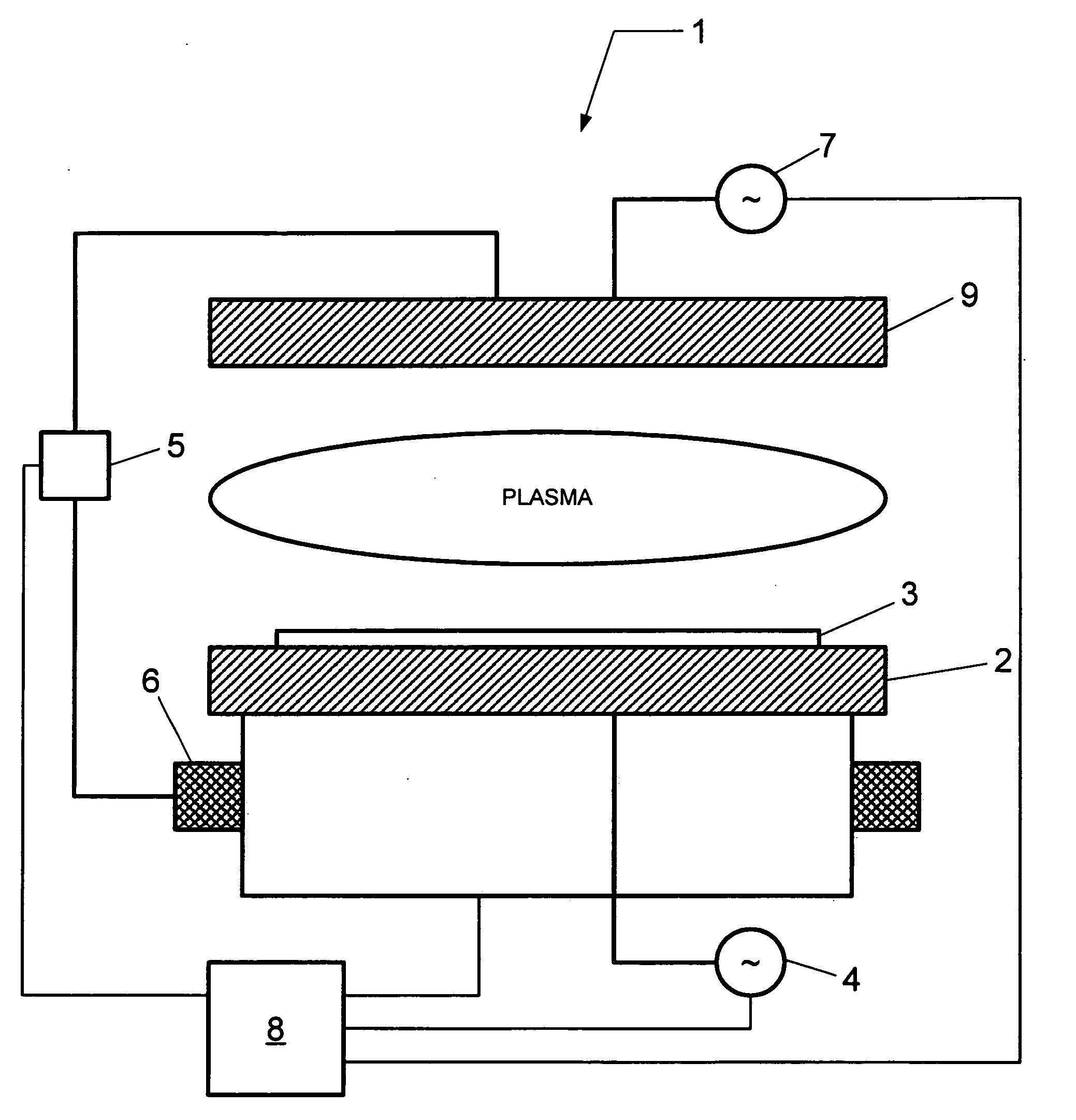
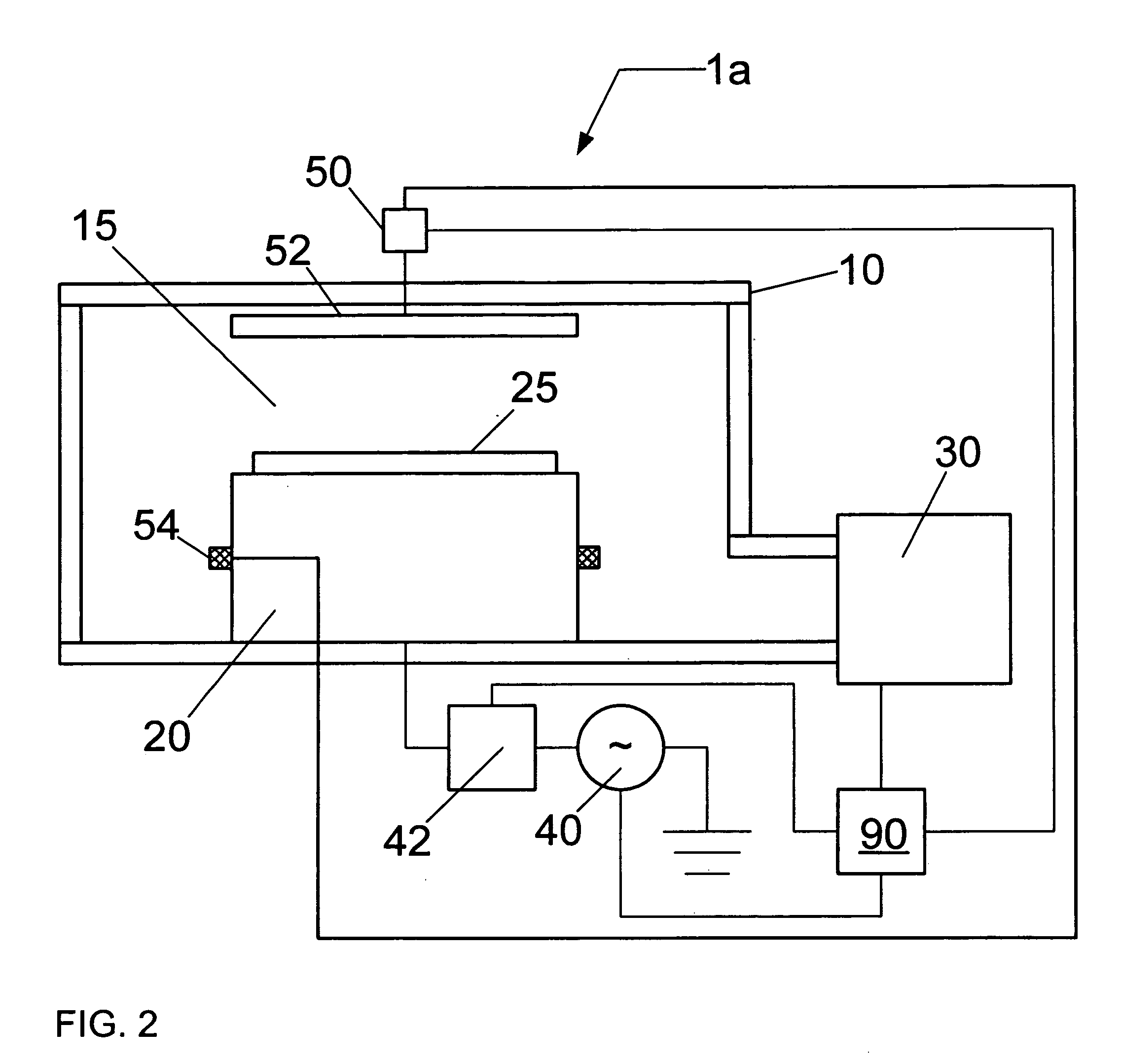
[0023]In the following description, for purposes of explanation and not limitation, specific details are set forth, such as a particular geometry of the plasma processing system and descriptions of various processes. However, it should be understood that the invention may be practiced in other embodiments that depart from these specific details.

[0024]In material processing methodologies, pattern etching comprises the application of a thin layer of light-sensitive material, such as photoresist, to an upper surface of a substrate that is subsequently patterned in order to provide a mask for transferring this pattern to the underlying thin film on a substrate during etching. The patterning of the light-sensitive material generally involves exposure by a radiation source through a reticle (and associated optics) of the light-sensitive material using, for example, a micro-lithography system, followed by the removal of the irradiated regions of the light-sensitive material (as in the case...


PUM

PropertyMeasurementUnit
DC voltageaaaaaaaaaa

Abstract

A method and apparatus for detecting the endpoint in a dry plasma etching system comprising a first electrode (e.g., upper electrode) and a second electrode (e.g., lower electrode) upon which a substrate rests is described. A direct current (DC) voltage is applied between the first electrode and a ring electrode surrounding the second electrode, and the DC current is monitored to determine the endpoint of the etching process. The DC current is affected by the impedance of the plasma, and therefore responds to many variations including, for example, the plasma density, electron/ion flux to exposed surfaces, the electron temperature, etc.

Description

BACKGROUND OF THE INVENTION[0001]1. Field of the Invention[0002]The present invention relates to a method and apparatus for plasma processing a substrate, and more particularly to a method and system for monitoring a plasma process in order to determine an endpoint to the plasma process.[0003]2. Description of Related Art[0004]During semiconductor processing, a (dry) plasma etch process can be utilized to remove or etch material along fine lines or within vias or contacts patterned on a substrate. The plasma etch process generally involves positioning a semiconductor substrate with an overlying patterned, protective layer, for example a photoresist layer, in a processing chamber. Once the substrate is positioned within the chamber, an ionizable, dissociative gas mixture is introduced within the chamber at a pre-specified flow rate, while a vacuum pump is throttled to achieve an ambient process pressure.[0005]Thereafter, plasma is formed when a fraction of the gas species present are...

Claims


Application Information

Patent Timeline
Patent Type & Authority Applications(United States)
IPC IPC(8): H01L21/66C23F1/00
CPCH01J37/32935H01L22/26H01J37/32963
Inventor PANDA, SIDDHARTHAWISE, RICHARDCHEN, LEESIEVERS, MICHAEL
Owner TOKYO ELECTRON LTD
Why Eureka
Try Eureka