Composite Electrode Active Material for Non-Aqueous Electrolyte Secondary Battery or Non-Aqueous Electrolyte Electrochemical Capacitor and Method for Producing the Same

a technology of electrochemical capacitor and secondary battery, which is applied in the direction of liquid electrolytic capacitor, electrochemical generator, cell component, etc., can solve the problems of inability to control the volume change of the material capable of forming an alloy with lithium, the inability to achieve practical use. , to achieve the effect of reducing the reduction of the conductivity of the electrode, high charge/discharge capacity and excellent cycle characteristics

Inactive Publication Date: 2008-03-13
PANASONIC CORP
View PDF1 Cites 33 Cited by
  • Summary
  • Abstract
  • Description
  • Claims
  • Application Information

AI Technical Summary

Benefits of technology

[0020] According to the present invention, it is possible to obtain an active material having a charge / discharge capacity that exceeds the theoretical capacity of graphite. Moreover, the conductivity between the active material particles can be maintained even after the material A capable of forming an alloy with lithium undergoes a great change in volume. Hence, the composite electrode active material of the present invention suppresses the reduction in conductivity of the electrodes due to expansion and contraction of the material A comprising an element capable of forming an alloy with lithium, and thus provides a non-aqueous electrolyte secondary battery having a high charge / discharge capacity and excellent cycle characteristics.
[0021] Further, the carbon nanofibers contained in the composite electrode active material of the present invention have an electric double layer capacity, and the material A capable of forming an alloy with lithium has a pseudocapacitance due to insertion and extraction of lithium. Hence, the composite electrode active material of the present invention provides a non-aqueous electrolyte electrochemical capacitor having a high charge / discharge capacity and excellent cycle characteristics.
[0022] For example, in the case where both the material A capable of forming an alloy with lithium and the material B comprising carbon are in a particulate state, carbon nanofibers are grown on at least one selected from the particle surface of the material A and the particle surface of the material B to coat each particle with the carbon nanofibers. By allowing the carbon nanofibers to be in an intertwined state, the particles are connected with each other via the carbon nanofibers at a large number of points. This enables the conductivity between the active material particles to be maintained even when the volume of the material A is changed greatly. In this case, even when the material A undergoes repeated expansion and contraction associated with charge / discharge and the particles thereof are crushed or pulverized, the particles of the formed fine powder are kept connected electrically via the carbon nanofibers. Hence, the conductivity between the particles is not reduced as much as in the conventional case.
[0023] The carbon nanofibers may be grown on both the particle surface of the material A and the particle surface of the material B, or grown on either one of them. For example, in the case where the material A with carbon nanofibers grown on the particle surface thereof and the material B without carbon nanofibers grown on the surface thereof are mixed, the particles of the material A are intertwined with each other via the carbon nanofibers. The particles of the material B subsequently enter the spaces between the particles of the material A, and the material B also becomes electrically connected with the carbon nanofibers. As a result, even when the volume change has been occurred, the conductivity between the active material particles can be maintained. However, an effect of securing the conductivity between the active material particles is enhanced when the carbon nanofibers are grown on the particle surface of the material A and the particle surface of the material B, since there are a larger number of electrical connection points.
[0024] In the composite electrode active material of the present invention, dissimilarly to the proposal of the Patent Document 2, in which the particles are covered with a rigid coating layer composed of a carbonaceous material, the particles are covered with layered carbon nanofibers having a cushioning effect. Structured as such, even when the particles of the material A have expanded, the carbon nanofiber layer can absorb the stress due to expansion. Accordingly, this suppresses breakage and exfoliation of the carbon nanofiber layer due to expansion of the material A and prevents the adjacent particles from being pushed strongly against each other. On the other hand, even when the particles of the material A have contracted, the damage to the conductivity between the adjacent particles can be suppressed since the carbon nanofibers are intertwined with each other.
[0025] Evidence is obtained that the growth rate of carbon nanofiber is significantly high when carbon nanofibers are grown on a composite material or a mixture of the material A and the material B comprising carbon. In this case, the growth rate of carbon nanofiber is extremely higher than that when the carbon nanofibers are grown exclusively on the material A. Hence, according to the present invention, it is possible to shorten the time required for growing carbon nanofibers. As a result, a more efficient production method of an electrode active material including the step of growing carbon nanofibers can be achieved, and thus the production efficiency of the electrode active material is significantly improved.

Problems solved by technology

However, none of the proposals are considered to be satisfactory in curbing the degradation associated with repeated charge / discharge cycles, and the practical use thereof has not yet been achieved.
For example, even when the surface of the particles made of a composite material of a material capable of forming an alloy with lithium and a carbonaceous material is coated with a carbonaceous material, it is impossible to control the volume change of the material capable of forming an alloy with lithium.
Furthermore, when the charge / discharge cycle is repeated, the coating layer ruptures or exfoliates and the composite material particles are crushed and pulverized, causing reduction in the conductivity between the particles and degradation in charge / discharge characteristics.
In view of the above, the techniques as proposed in Patent Documents 1 and 2 are not suitable for practical use.
Hence, this document fails to provide a solution to a problem arising when such a material whose volume change is great as described above is used as an electrode active material.

Method used


Image

  • Composite Electrode Active Material for Non-Aqueous Electrolyte Secondary Battery or Non-Aqueous Electrolyte Electrochemical Capacitor and Method for Producing the Same
  • Composite Electrode Active Material for Non-Aqueous Electrolyte Secondary Battery or Non-Aqueous Electrolyte Electrochemical Capacitor and Method for Producing the Same
  • Composite Electrode Active Material for Non-Aqueous Electrolyte Secondary Battery or Non-Aqueous Electrolyte Electrochemical Capacitor and Method for Producing the Same

Examples


example 1

[0114] Herein, silicon monoxide (SiO) was used as the material A comprising an element capable of forming an alloy with lithium, and artificial graphite was used as the material B comprising carbon.

[0115] 100 parts by weight of silicon monoxide particles (reagent manufactured by Wako Pure Chemical Industries, Ltd.) obtained by grounding and classifying beforehand so as to have a mean particle size of 10 μm and 100 parts by weight of artificial graphite (manufactured by TIMCAL Ltd., SLP30, mean particle size 16 μm) were dry mixed in a mortar for 10 minutes.

[0116] 100 parts by weight of the resultant mixture was mixed with a solution obtained by dissolving 1 part by weight of nickel nitrate (II) hexahydrate (guaranteed reagent) manufactured by Kanto Chemical Co., Inc in deionized water. A mixture of the silicon monoxide particles, the artificial graphite and the nickel nitrate solution was stirred for one hour and then the water was removed with an evaporator to allow nickel nitrate ...

example 2

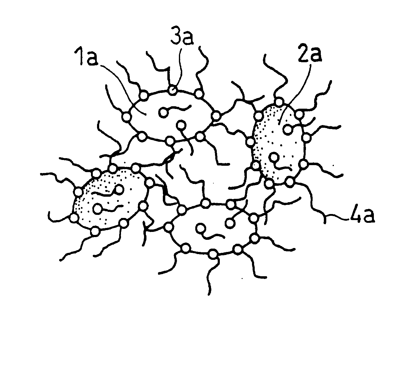
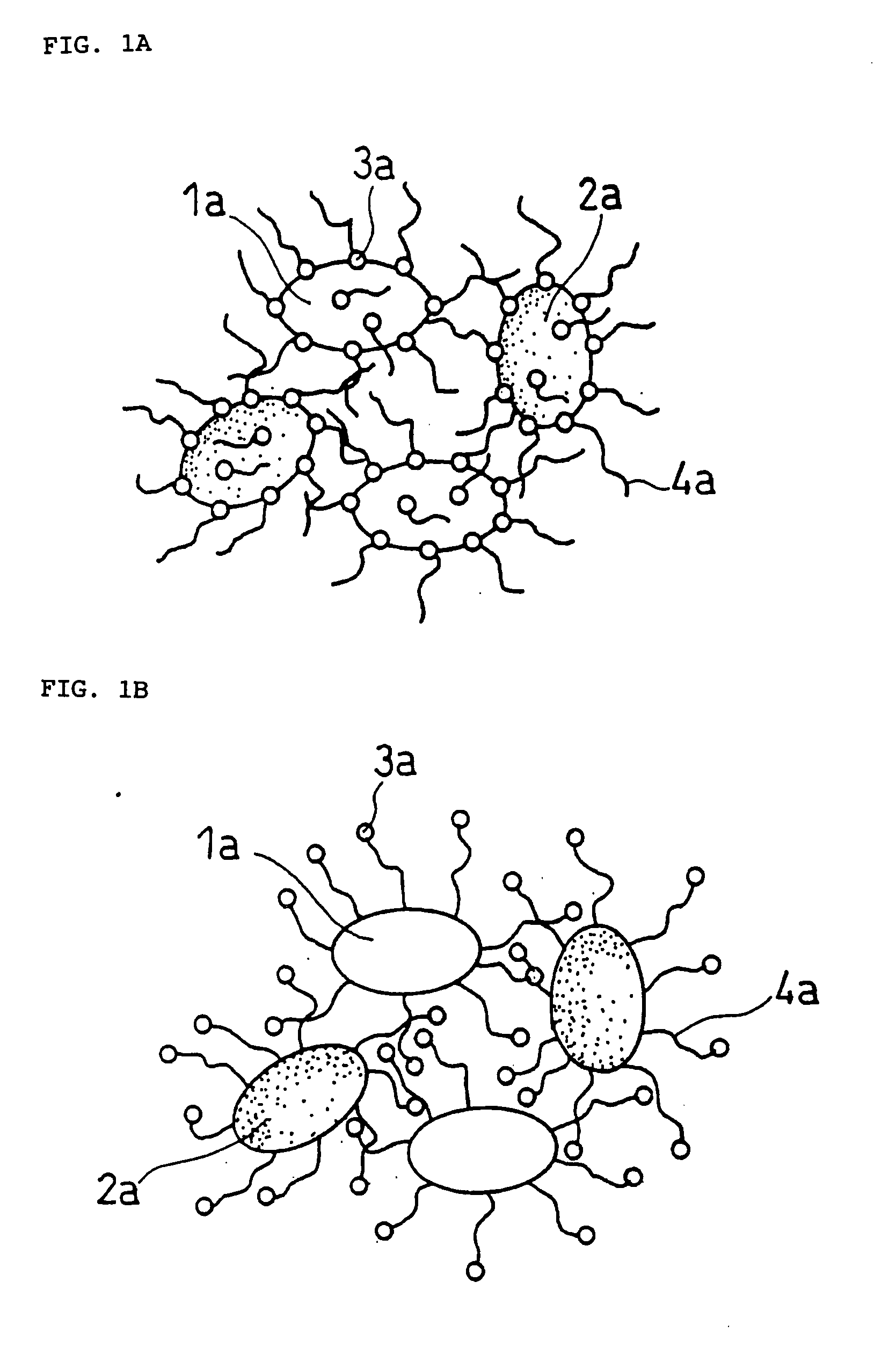
[0120] The same operations as in Example 1 were carried out except that the amount of artificial graphite with respect to 100% by weight of silicon monoxide particles was decreased to 20% by weight, whereby a composite negative electrode active material B as illustrated in FIG. 1 was obtained. The fiber diameter and the fiber length of the grown nanofibers, the weight proportion of the carbon nanofibers to the whole composite electrode active material and the particle size of the catalyst particles were substantially the same as those in Example 1.

example 3

[0121] 100 parts by weight of artificial graphite (manufactured by TIMCAL Ltd., SLP30, mean particle size 16 μm) and 110 parts by weight of tin acetate (II) (manufactured by Kanto Chemical Co., Inc., first class reagent) are mixed together with an aqueous acetic acid solution. The resultant mixture was stirred for one hour and then the acetic acid and the water were removed with an evaporator to allow tin acetate (II) to be carried on the surface of the graphite particles.

[0122] The graphite particles carrying tin acetate were placed in a ceramic reaction vessel, and the temperature was raised to 400° C. in the presence of argon gas. Thereafter, the temperature was held at 400° C. for 10 hours to reduce the tin acetate (II). The interior of the reaction vessel was then cooled down to room temperature, whereby composite material particles of graphite and tin oxide were obtained.

[0123] As a result of analysis of the composite material particles thus obtained using an SEM, an XRD, an...


PUM

PropertyMeasurementUnit
particle sizeaaaaaaaaaa

Abstract

Disclosed is a composite electrode active material for non-aqueous electrolyte secondary batteries or non-aqueous electrolyte electrochemical capacitors which contains a material A containing an element capable of forming an alloy with lithium, a material B containing carbon excluding carbon nanofiber, a catalyst element for promoting the growth of carbon nanofiber, and carbon nanofibers grown on at least one selected from the surface of the material A and the surface of the material B.

Description

TECHNICAL FIELD [0001] The present invention relates to a composite electrode active material for use in non-aqueous electrolyte secondary batteries or non-aqueous electrolyte electrochemical capacitors and a method for producing the same. Specifically, the present invention relates to a composite electrode active material including a material with carbon nanofibers grown on the surface thereof. The composite electrode active material of the present invention provides non-aqueous electrolyte secondary batteries or non-aqueous electrolyte electrochemical capacitors having excellent charge / discharge characteristics and cycle characteristics. BACKGROUND ART [0002] As electronic devices have been progressively made portable and cordless, there has been growing expectation for non-aqueous electrolyte secondary batteries that are small in size and light in weight and have a high energy density. At present, carbonaceous materials such as graphite come into practical use as negative electro...

Claims


Application Information

Patent Timeline
Patent Type & Authority Applications(United States)
IPC IPC(8): H01G9/04H01M10/38H01M4/38H01G11/36H01G11/38H01G11/50H01M4/13H01M4/587H01M10/052H01M10/0525H01M10/0566
CPCB82Y30/00Y02E60/13C01B31/0206D01F9/127H01G11/36H01G11/38H01M4/13H01M4/364H01M4/366H01M4/38H01M4/405H01M4/587H01M4/625H01M10/052H01M2004/027Y02E60/122H01G11/50B82Y40/00H01M4/386H01M4/387C01B32/15Y02E60/10H01M4/583
Inventor MATSUDA, HIROAKIISHIDA, SUMIHITOYOSHIZAWA, HIROSHI
Owner PANASONIC CORP
Why Eureka
Try Eureka