
Fibrillated polyolefin foam

a technology of foam and polyolefin, applied in the field of production of polyolefin foam, can solve the problems of limited stability and resiliency of air-lay materials, high density of wet laid materials, and high bulk of air-lay materials

Active Publication Date: 2008-03-27
DOW GLOBAL TECH LLC
View PDF88 Cites 82 Cited by
  • Summary
  • Abstract
  • Description
  • Claims
  • Application Information

AI Technical Summary

Benefits of technology

[0045]The multi-block interpolymers disclosed herein may be differentiated from conventional, random copolymers, physical blends of polymers, and block copolymers prepared via sequential monomer addition, fluxional catalysts, and anionic or cationic living polymerization techniques. In particular, compared to a random copolymer of the same monomers and monomer content at equivalent crystallinity or modulus, the interpolymers have better (higher) heat resistance as measured by melting point, higher TMA penetration temperature, higher high-temperature tensile strength, and / or higher high-temperature torsion storage modulus as determined by dynamic mechanical analysis. Properties of infill may benefit from the use of embodiments of the multi-block interpolymers, as compared to a random copolymer containing the same monomers and monomer content, the multi-block interpolymers have lower compression set, particularly at elevated temperatures, lower stress relaxation, higher creep resistance, higher tear strength, higher blocking resistance, faster setup due to higher crystallization (solidification) temperature, higher recovery (particularly at elevated temperatures), better abrasion resistance, higher retractive force, and better oil and filler acceptance.
[0141]Advantages of embodiments of the disclosure may include one or more of the following. The reticulated morphology may allow for larger foam surface openings that may result in faster liquid absorption and faster liquid strike through. The larger void spaces may result in lower capillary pressure for reduced liquid retention versus traditional froth foam morphology. The foam described in herein may exhibit superior wet and dry tensile strength and superior wet collapse compared to cellulose based fiber systems. Additionally, the elastomeric nature of various foams may also allow the foam to retain shape. Advantageously, in some embodiments, the fibers may act as a collapse stabilizing agent, reducing froth collapse during film formation and / or reducing dry foam collapse.

Problems solved by technology

For example, wet laid materials generally suffer from high density due to the planar arrangement of the fibers.
Air laid materials tend to have high bulk, but are limited in their stability and resiliency in addition to limitations of porosity.
Traditional fluff pulp and creped tissue offer high void volumes and are hydrophilic, but collapse when wetted.
However, limitations on the speed at which the fluid is absorbed (insult rate) exist for these foams.
Another challenge in the formulation of frothed type foams is inconsistent and undesired foam collapse during the drying process, thus making the properties of the foam difficult to control.

Method used


Image

  • Fibrillated polyolefin foam
  • Fibrillated polyolefin foam
  • Fibrillated polyolefin foam

Examples


example 1

[0130]Three foam samples are prepared according to the above procedure. Sample 1 foam contains no fibers and uses the above described 2-1-1 dispersion of AFFINITY™ EG 8200 (POD 8102, The Dow Chemical Company, Midland, Mich.) and 1.5% STEOL® based on polymer solids. Samples 2 and 3 use a 40% fiber loading with polyethylene fibers (Polyethylene Fiber Type E available from MiniFIBERS, Inc., Johnson City, Tenn.), in addition to the 1.5% STEOL®, both based on polymer solids. Sample 2 is made with 2-1-1 POD 8102 dispersion whereas Sample 3 uses a 2-1-2 POD 8102 dispersion.

[0131]Strike through experiments, testing the speed at which a liquid passes through the foam structure, and Absorbent Capacity Index (ACI) measurements are carried out on these foam samples prepared in accordance with the details disclosed above.

[0132]The liquid used for the strike through measurements is a 5.0 mL sample of synthetic urine (as described in U.S. Pat. No. 5,260,345) at 23° C. with a foam sample size of 50...

example 2

[0136]Foam samples are synthesized in accordance with the protocol outlined above. Polyolefin dispersions (POD 8102) are variably diluted and incorporate varied fiber loadings with polyethylene pulp (Polyethylene Fiber Type E available from MiniFIBERS, Inc., Johnson City, Tenn.). Fiber loadings shown in Table 3 are based upon the weight of polymer solids. Sample foams are 15.3 cm×10.2 cm. These samples are subjected to 45 Degree Run-off test carried out by placing the foam sample on a surface at a 45 degree angle and introducing two 80 mL liquid insults to the top of the foam, and collecting and measuring the quantity of any liquid run-off not absorbed by the foam. The liquid insults are introduced five minutes apart, and the run-off measurements are reported as 1st and 2nd Run-off, respectively. The foam collapse represents the amount of froth collapse during curing. The liquid insult is synthetic urine formulated as 0.03 weight percent calcium chloride, 0.08 weight percent magnesi...

example 3

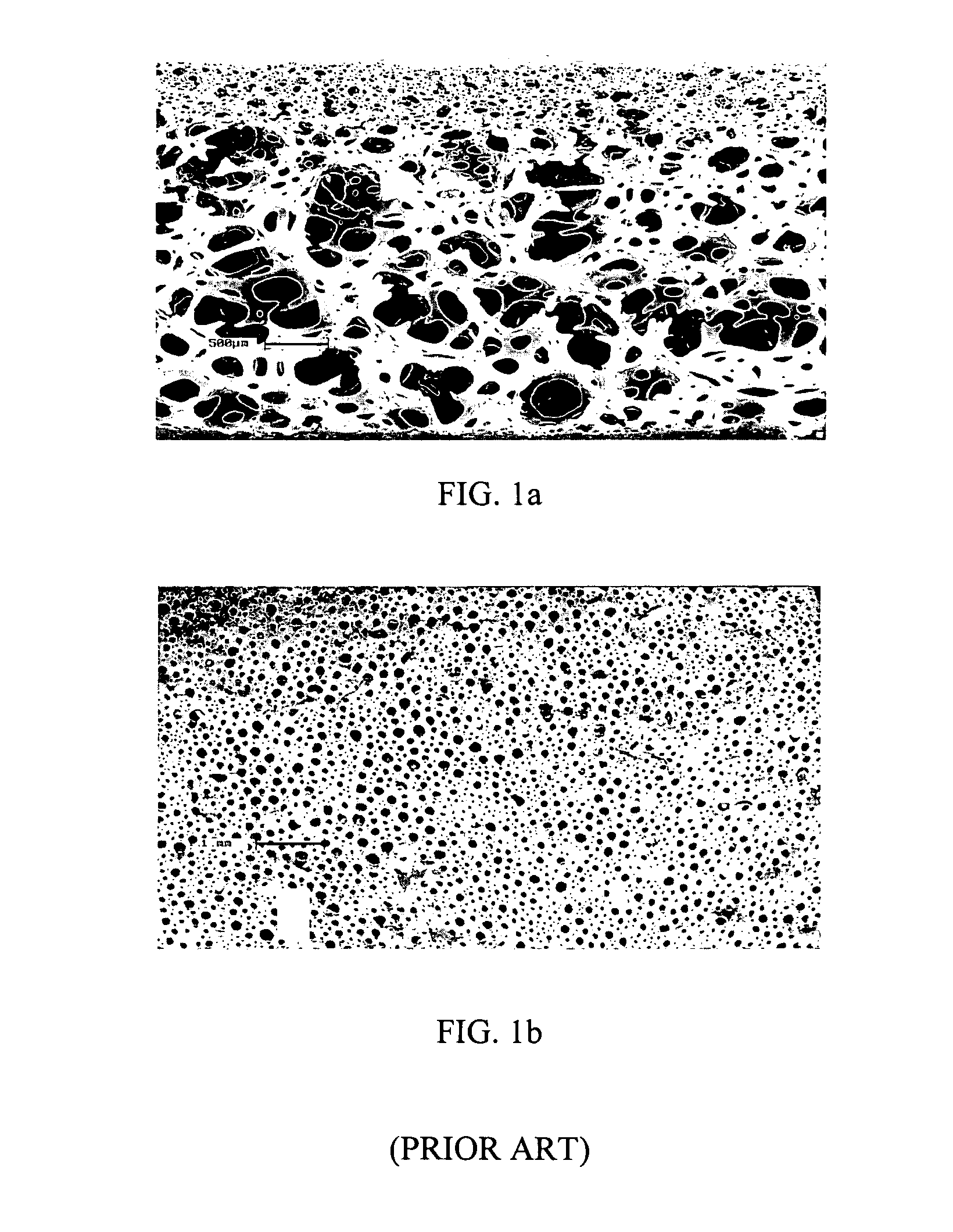
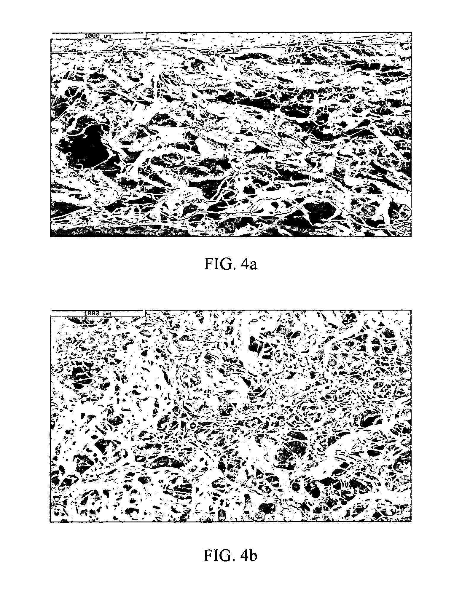
[0138]SEM images of samples of polyolefin foams made in accordance with the above outlined protocol are illustrated in FIGS. 4a and 4b. The foam formed from an aqueous dispersion of AFFINITY™ with incorporated polyolefin fibers displays a novel, non-cellular, fibrillated structure. The morphology of the foams may be characterized as having a high degree of randomness and larger surface openings as compared to the traditional PFFs shown in FIGS. 1a-b. The cross-section of the foam shown in FIG. 4a also displays a non-cellular architecture with non-woven fibrils and large void spaces. The larger surface openings, as shown in FIG. 4b, may allow for faster liquid strike through and the larger void spaces may result in lower capillary pressure for liquid retention.

[0139]High resolution SEM images of the foam struts show that the polyethylene fibers are substantially encapsulated by the AFFINITY™ polymer, as shown in FIGS. 5 and 6. In FIG. 5, a high resolution image of a strut in the foam...


PUM

PropertyMeasurementUnit
Lengthaaaaaaaaaa
Lengthaaaaaaaaaa
Fractionaaaaaaaaaa

Abstract

A method for generating a thermoplastic foam from an aqueous dispersion, the aqueous dispersion comprising a thermoplastic resin, water, and a dispersion stabilizing agent, the method including: adding at least one froth stabilizing surfactant to the aqueous dispersion to form a mixture; adding a fiber to the mixture; and frothing the mixture to create a froth, removing at least a portion of the water in the froth to create a foam, wherein the foam generated has a non-cellular fibrillated morphology. In another aspect, embodiments disclosed herein relate to a foam having a thermoplastic-based, fibrillated, non-cellular structure, wherein the foam has an average density of about 0.02 g / cm3 to about 0.07 g / cm3. In certain embodiments, the foam may be used in an absorbent article.

Description

BACKGROUND OF DISCLOSURE[0001]1. Field of the Disclosure[0002]The present disclosure relates generally to the production of polyolefin foams for applications in absorbent materials.[0003]2. Background Art[0004]Absorbent materials are used in many personal care articles ranging from baby diapers to hygiene pads for adult incontinence and feminine needs. The efficacy of absorbent articles is dependent on several properties of the core absorbent material including high void volumes, hydrophilicity, wet resiliency, speed of absorption, and the ability to maintain void volume when wet. In diapers, for example, the absorbent core must quickly acquire fluids, distribute it in the void space, and act as a temporary reservoir until the super absorbent polymer (SAP) can absorb and hold the fluid.[0005]The properties of absorbent materials are generally affected by the method with which they are deposited on their supporting surface. For example, wet laid materials generally suffer from high d...

Claims


Application Information

Patent Timeline
IPC IPC(8): C08L75/00
CPCA61L15/24A61L15/425B29C67/202C08J9/0085C08J9/30C08L23/00C08J9/22C08J9/35A61L15/42
Inventor VAN SUMEREN, MARK W.STOCKTON, LUTHERMACHELSKI, SUE
Owner DOW GLOBAL TECH LLC
Learn More