Van Nimwegen efficient pollution free internal combustion engine

a pollution-free, internal combustion engine technology, applied in the direction of machines/engines, liquid fuel feeders, fuel injecting pumps, etc., can solve the problems of high cost and storage problems associated with cryogenic oxygen use, short life of emulsions, and questionable stability of emulsions, etc., to achieve high efficiency, eliminate pollutants from exhaust, and high efficiency

Inactive Publication Date: 2008-04-17
VAN NIMWEGEN ROBERT R
View PDF5 Cites 35 Cited by
  • Summary
  • Abstract
  • Description
  • Claims
  • Application Information

AI Technical Summary

Benefits of technology

[0014]The object of this invention is to provide a highly efficient vehicular engine which has eliminated pollutants from the exhaust. The CI diesel engine cycle is most desirable because of its higher efficiency and with the modifications proposed by this invention, the specific power can be increased and the particulates (soot and smoke) will be eliminated from the exhaust. This invention introduces a means of reforming the liquid fuel sprayed into the precombuster (reformer) with steam formed when water is injected into the high temperatures existing in the reformer. Water is introduced as a coolant into the exhaust cooler 32 (Boiler) by a high pressure pump, driven by the turbocharger, capable of handling water and vapor. At the fuel injection point, shortly before TDC, approximately one third of the total charge of air is in the reformer. Fuel has been injected prior to the water by a prescribed delay to allow time for the initiation of combustion. The principle of reforming fuels has long been practiced in the manufacture of blue gas (water gas). A weight ratio of water to hydrocarbon fuel of 1.2 or larger has been found to be acceptable. Exhausts of current auto and truck CI engines operating on hydrocarbon fuels produce pollutants that include particulates, hydrocarbons, carbon monoxide, nitrous oxides, carbon dioxide as well as obnoxious smell and exhaust noise. This invention has considered each of these pollutants and has resulted in a design capable of providing a substantial reduction to all of these pollutants and is suitable for vehicular propulsion.
[0015]1. Particulates (soot, smoke, dust and small pieces of metal) will be reduced in the exhaust by the following means. Smoke and soot are formed by the incomplete combustion of the carbon in the fuel. In a CI engine the inlet air is compressed by a compression ratio of 25:1 resulting in a pressure of over 2000 psia and an air temperature in the reformer in excess of 2000° F. Fuel sprayed into the combustion chamber burns only around the surface of a fuel droplet where the fuel-air ratio falls within the narrow band required for combustion. Hydrogen burns first and if there is insufficient oxygen remaining locally to convert the carbon to carbon monoxide and carbon dioxide, free carbon will remain as soot and smoke. Visible smoke appears when the fuel-air ratio is equal to, or exceeds, 50 percent of stoichometric. In the proposed invention high velocity water will be injected at approximately the same time as the fuel, physically and intimately mixing to assist in the completion of the chemical reaction. Because of the high temperature existing in the reformer at the time of injecting the water it will flash into steam, disassociating into hydrogen, oxygen and water vapor, providing the additional oxygen required for the complete oxidation of the carbon, preventing the smoke from forming. The water acts as a catalyst during the combustion process and is condensed, removed and recovered from the exhaust. In the process of condensation water droplets will neucleate on any existing solid exhaust particles and will be removed by the water separator.
[0016]2. Hydrocarbons, in some instances, result from unburned fuel spray hitting a cooled cylinder wall forming deposits on the combustion chamber walls....

Problems solved by technology

However, the disadvantage of this system, particularly in small, high speed diesels, is that the emulsions have been proven to have a very short life and it is questionable whether the emulsion would remain stable, even long enough to permit it to enter the combustion zone.
Disadvantages of this system will be the high cost and storage problems associated with the use of cryogenic oxygen.
Exhausts of current auto and truck CI engines operating on hydrocarbon fuels produce pollutants that include particulates, hydrocarbons, carbon monoxide, nitrous oxides, carbon dioxide as well as obnoxious smell and exhaust noise.
Smoke and soot are formed ...

Method used


Image

  • Van Nimwegen efficient pollution free internal combustion engine
  • Van Nimwegen efficient pollution free internal combustion engine
  • Van Nimwegen efficient pollution free internal combustion engine

Examples


main embodiment

Operation—Main Embodiment

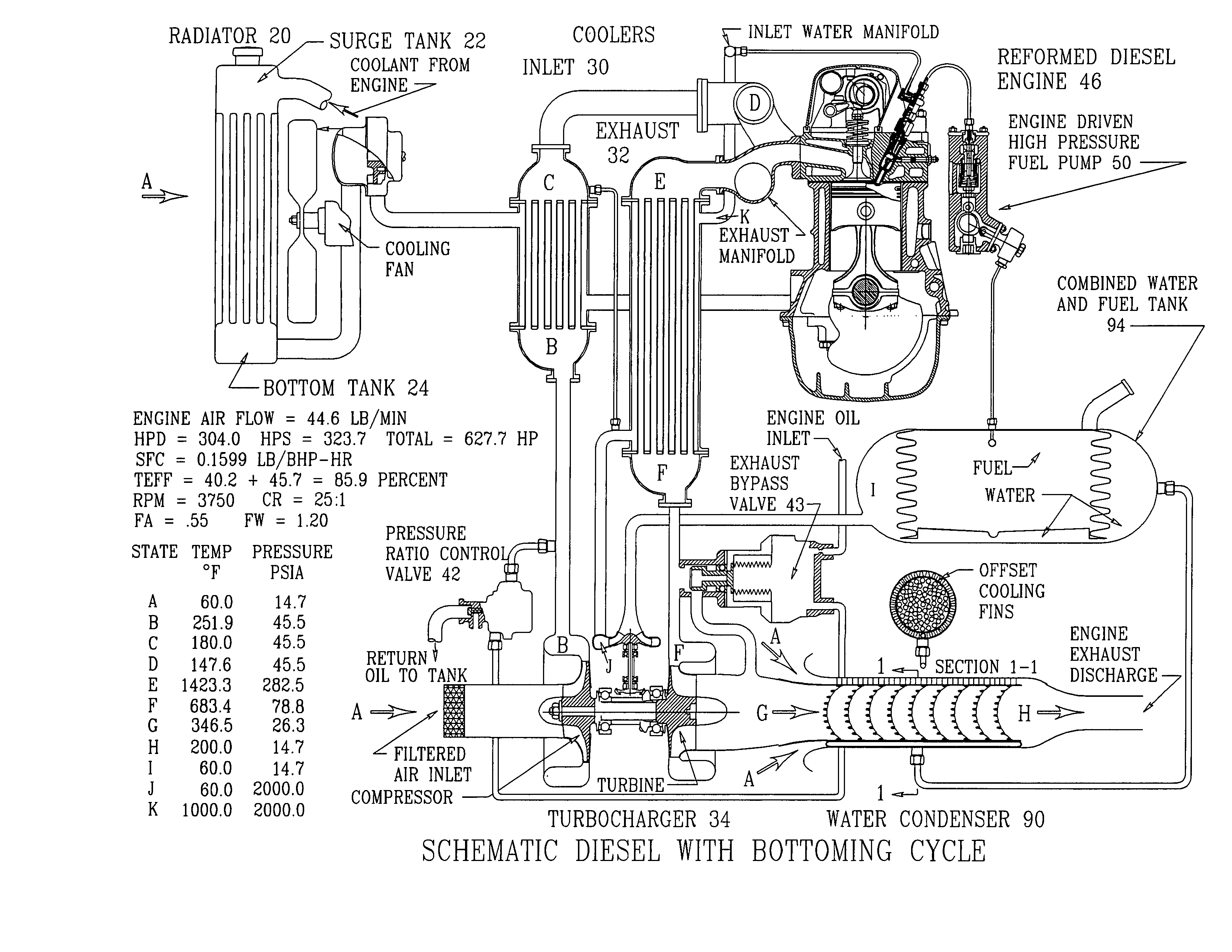
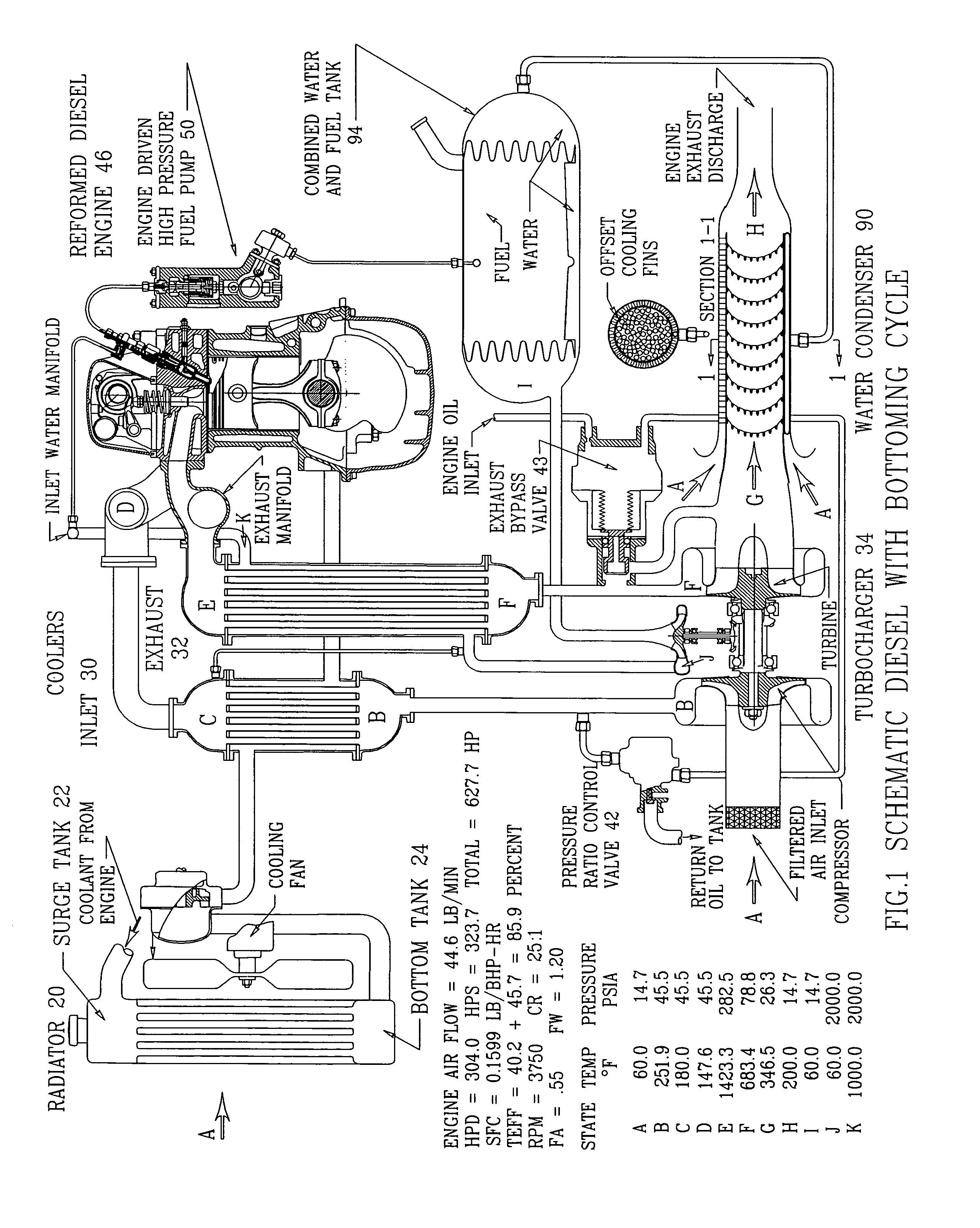
[0037]FIG. 1. is a Schematic Drawing of the Compression Ignition Engine Cycle. This is a cycle definition used for the performance analysis of the internal combustion engine as concieved for this invention with turbocharging, intercooling, precombuster (reformer), two cycle operation, exhaust cooling with a water seperator in the exhaust followed by two cycle as a steam engine. An extensive analytical analysis of each of the components is required to arrive at a selection for the optimum engine to be used for a specific vehicular design. Many variables can be studied to understand their influence on reducing the pollutants discharged into the environment. In the example to be presented, the turbocharger compressor pressure ratio, the diesel compression ratio, intercooling, FA ratio and exhaust cooling will be discussed. The cycle analysis consists of the following eight designated state points. From ambient condition to State A, represents the predicted pres...

example

[0042]A modification of the Mercedes Benz 200d, with a Garrett turbocharger, was selected as an example for a CI automotive engine that could be used for the analytical study of the theroy of water injection and the introduction of a bottoming steam engine cycle on the third stroke of a four cycle engine. This modified six cylinder diesel engine with precombuster has a bore of 3.710 inches piston diameter and a stroke of 3.937 inches. Assumed turbocharger pressure ratio of 3.0:1 and an engine cycle compression ratio of 25:1. Operating speed of 3750 RPM. Diesel fuel used C10H22 with a LHV of 19,192 BTU / lb. Intake Valve Open at 48 degrees with fuel injected at 167 degrees. Shower Head Area of 0.032 square inches. Exhaust valve open at 308 degrees. The analysis was based on the assumption that the duration of the fuel injection is proportional to the fuel-air ratio. The start of water injection has been delayed by a prescribed amount to allow ignition of the fuel to start in the reform...


PUM


Abstract

Internal combustion engines, both compression ignition (CI) and spark ignition (SI), four cycle and turbocharged, are defined with the proposed patented modifications to improve environmental acceptability. Thermal efficiency has been more than doubled at the maximum power design point. The CI engine 75.8 percent and the SI engine 72.7 percent. The particulates (smoke), nitrus oxide, and carbon monoxide have been reduced to a trace for both engine types. With the improved thermal efficiency the carbon dioxide produced per horsepower is less than half of the current designs. Exhaust noise and obnoxious smell has been eliminated for both engine types. These predicted improvements are based on the use of existing fuels. A byproduct of the design will be the recovery of the distilled water resulting from the products of combustion.
A fuel tank is defined which collects the condensed water and varies the fuel storage volume to that required for the remaining fuel. With this design no empty space exists for the formation of fuel vapor which is an explosive safety hazard.

Description

BACKGROUND OF INVENTION[0001]1. Field of Invention[0002]Vehicular pollution is still one of the greatest dangers to our environment today. Studies have indicated that health is adversely affected to the extent that particulate pollution may be responsible for up to 60,000 deaths annually in the nation, more than the number of traffic fatalities. California clean air standards call for less than 50 micrograms per cubic meter per 24 hours, a standard three times more strict than the current federal standard.[0003]This invention relates generally to internal combustion vehicular engines and more particularly to the Diesel Compression Ignition (CI) Engine, selected because of its inherently higher cycle efficiency and the desirable use of diesel fuel instead of gasoline. The CI engines higher compression ratio results in a more efficient cycle than the Otto Cycle Spark Ignition (SI) Engine. However, the specific power (horsepower / pound air per minute) has been limited by the introductio...

Claims


Application Information

Patent Timeline
IPC IPC(8): F02B29/04
CPCF01N3/005F01N3/02F01N5/02F02B29/0443F02B37/18F02M37/0082Y02T10/20F02M53/06F02M59/102F02M61/06Y02T10/146Y02T10/16F02M43/04Y02T10/12
Inventor VAN NIMWEGEN, ROBERT R.
Owner VAN NIMWEGEN ROBERT R
Why Eureka
Try Eureka