Magnetic recording head and media overcoat

a magnetic recording and media overcoat technology, applied in the field of hard disk drive fabrication, can solve the problems of unavoidable contact between the disk surface and the head, damage to the head and the disk, loss of recorded information on the disk, etc., and achieves poor adhesion with the substrate materials of the head and other substrates

Inactive Publication Date: 2008-08-07
SAE MAGNETICS (HK) LTD
View PDF13 Cites 19 Cited by
  • Summary
  • Abstract
  • Description
  • Claims
  • Application Information

AI Technical Summary

Benefits of technology

[0011]The first object of the present invention is to provide a thin protective layer for a magnetic read / write head or a magnetic recording medium to protect them from inadvertent contact between the head and the medium surface.

Problems solved by technology

Maintaining such a small spacing between a rapidly spinning disk and a read / write head literally flying above it is difficult and an occasional contact between the disk surface and the head is unavoidable.
Such contact, when it does occur, can lead to damage to the head and the disk and to the loss of recorded information on the disk.
Conventionally, DLC coatings thicknesses are greater than 50 angstroms and for that thickness range there is a high degree of internal stress, leading to poor adhesion with the substrate materials of the head as well as to other substrates to which they may be bonded.
1. Electrical isolation property. For magnetic heads, electrical isolation must be provided for the magnetic metal alloy layers, such as those layers comprising a magnetoresistive read head based on the giant magnetoresistance (GMR) effect, or those comprising a device based on the tunneling magnetoresistive (TMR) effect. Electrical short circuits between these layers and surrounding HDD components will damage the head or similar device. For this reason, the protection layers, especially the underlayer, should be insulating or semi-insulating. However, due to the semiconductor properties of Si, the surface shunting of a Si adhesion layer can introduce noise, such as the so-called popcorn noise, into the GMR or TMR reader.
2. Anti-corrosion property. DLC films, particularly those produced through the filtered cathodic vacuum arc (FCVA) process of the prior art, are often embedded with micro- or nano-particles. These particles can result in pinholes and corrosion of the materials used in forming the magnetically active layers, such as NiFe and NiCoFe. The anti-corrosion property of the underlayer, if it can be provided, is therefore of crucial importance to maintaining the performance integrity of the sensor.
3. Anti-wear property. With the total thickness of the adhesion layer and the DLC layer being reduced to the sub-30 angstrom range, literally every atom counts for the protection. It is therefore very important that the adhesion layer has both chemical stability for corrosion protection and high hardness for tribological advantage. It is the purpose of the present invention to provide a new class of materials as adhesion layers to replace the Si and related materials described in the prior art cited above.

Method used


Image

  • Magnetic recording head and media overcoat
  • Magnetic recording head and media overcoat
  • Magnetic recording head and media overcoat

Examples


first preferred embodiment

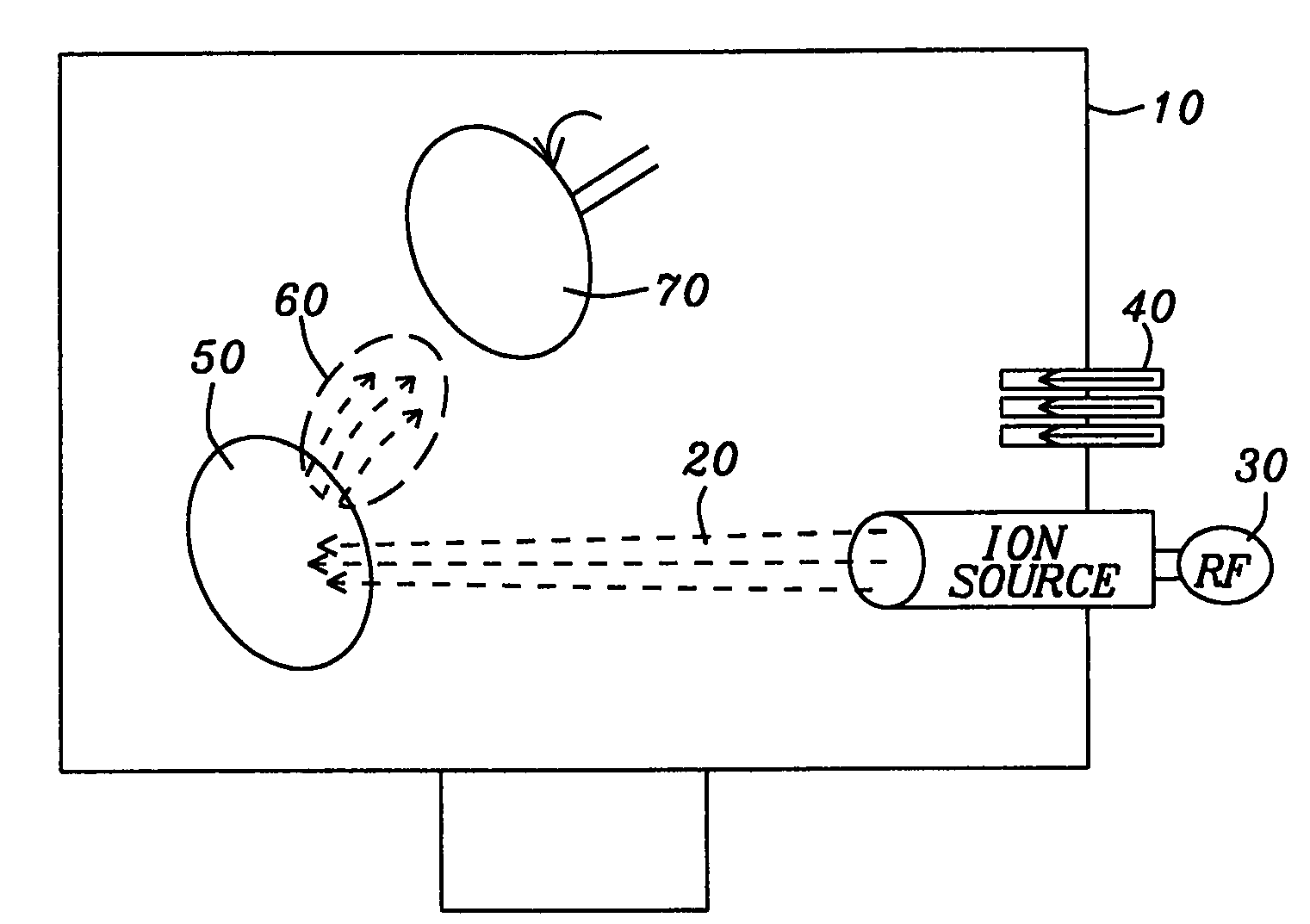
[0040]Referring now to FIG. 7, there is shown a schematic perspective drawing of an apparatus within which the protective bilayer of the present invention can be formed on a magnetic read / write head or recording medium.

[0041]The first preferred embodiment of this invention uses a deposition chamber (10) into which an ion beam, which in this embodiment is an Ar+ beam (20), is injected. The beam is produced by a RF source (30) and accelerated by voltages that range from 300 V to 1200 V. Injection ports (40) allow the injection of O2 and N2 gases into the chamber (10) with flow rates between 0 and 20 sccm, and different ratios, x / y, depending upon the desired form of the SiOxNy underlayer. The Ar+ beam is directed at a sputtering target of SiO2 (50) and the sputtered atoms (60) impinge on a rotatably mounted deposition target (70) that can be read / write heads, a plurality of which can be mounted as uncut sliders on a rotatable holder that can be rotated for uniformity of the deposition...

second preferred embodiment

[0042]In a second preferred embodiment, the apparatus of FIG. 8 is used as above, but the sputtering target material (50) is Si3N4. A ion beam, which in this embodiment is an Ar+ beam (20) is injected using voltages between 300 V and 1200 V and the O2 and N2 gases are injected into the chamber (10) with flow rates between 0 and 20 sccm, and different ratios, x / y, depending upon the desired form of the SiOxNy underlayer. The Ar+ beam is directed at a sputtering target of Si3N4 (50) and the sputtered Si and N atoms (60) impinge on the rotatably mounted deposition target (70) of read / write heads in the presence of the injected O2 and N2 gases to produce the desired SiOxNy underlayer. A plurality of the read / write heads are mounted as a plurality of uncut sliders on a rotatable holder for uniformity of the deposition. Alternatively, (70) can also be a magnetic recording medium such as a magnetic disk. Values of x between 0.02 and 2.0 and values of y between 0.01 and 1.5 have produced un...

third preferred embodiment

[0044]The third preferred embodiment of this invention uses the apparatus of FIG. 7, comprising a deposition chamber (10) into which an ion beam can be injected while injection ports (40) allow the injection of O2 and N2 gases with flow rates between 0 and 20 sccm, and different ratios, x / y, depending upon the desired form of the SiOxNy underlayer. In this embodiment, however, the ion beam is a high energy scanning, focused ion beam (20) that is directed at a sputtering target of Si (50) and the sputtered atoms (60) impinge on the rotatably mounted deposition target (70) of read / write heads that are mounted as uncut sliders on a rotatable holder for uniformity of the deposition. Alternatively, (70) can also be a magnetic recording medium such as a magnetic disk. To avoid poisoning the sputtering target and to eliminate hysteresis effects associated with the deposition, there is used a high energy scanning focused ion beam as described by T. Nyberg et al. (US Patent Application 2004 / ...


PUM

PropertyMeasurementUnit
thicknessaaaaaaaaaa
thicknessaaaaaaaaaa
voltageaaaaaaaaaa

Abstract

A method for forming a protective bilayer on a substrate that is a magnetic read/write head or a magnetic recording medium. The bilayer is formed as an adhesion enhancing and corrosion resistant underlayer and a protective diamond-like carbon (DLC) overlayer. The underlayer is formed of silicon oxynitride, having the general formula SiOxNy, where x can be within the range between 0.02 and 2.0 and y is in the range between approximately 0.01 and 1.5. By adjusting the values of x and y the underlayer contributes to such qualities as strong chemical bonding between the substrate and the DLC, wear and corrosion resistance, chemical and mechanical stability and low electrical conductivity. The underlayer may be formed by various methods such as reactive ion sputtering, plasma assisted chemical vapor deposition, reactive pulsed laser deposition, plasma surface treatment and plasma immersion ion implantation.

Description

RELATED PATENT APPLICATION[0001]This application is related to Docket Number SM 06-006, Filing Date Jan. 18, 2007, Ser. No. 11 / 655,025, assigned to the same assignee as the present application.BACKGROUND OF THE INVENTION[0002]1. Field of the Invention[0003]This invention relates to the fabrication of hard disk drives (HDD), particularly to a method of protecting a magnetic head and magnetic disks by use of a diamond-like coating on an underlayer that also enhances adhesion and serves as a corrosion barrier.[0004]2. Description of the Related Art[0005]Reducing the head-to-disk spacing (fly height) between a magnetic read / write head and the surface of a magnetic disk rotating beneath it has been one of the major approaches in achieving ultra-high recording density in a hard disk drive (HDD) storage system. For a commercially available HDD with 160 GBytes capacity, the fly height is on the order of 10 nanometers (nm). Maintaining such a small spacing between a rapidly spinning disk and...

Claims


Application Information

Patent Timeline
Patent Type & Authority Applications(United States)
IPC IPC(8): C23C16/34
CPCC23C14/0036C23C14/024C23C14/0605C23C14/0676Y10T428/115G11B5/40G11B5/72G11B5/8408G11B5/3106G11B5/7264G11B5/127G11B21/02G11B21/21
Inventor CHENG, SHIDEFENG, ZHUCHA, ELLIS T.
Owner SAE MAGNETICS (HK) LTD
Why Eureka
Try Eureka