

Lubricant for compression type refrigerating machine and refrigerating device using same
a technology of refrigerating machine and lubricant, which is applied in the direction of lubricant composition, refrigeration machines, light and heating apparatus, etc., can solve the problems of ozone layer, environmental pollution, environmental pollution, etc., and achieve high viscosity index and good compatibility
- Summary
- Abstract
- Description
- Claims
- Application Information
AI Technical Summary
Benefits of technology
Problems solved by technology
Method used
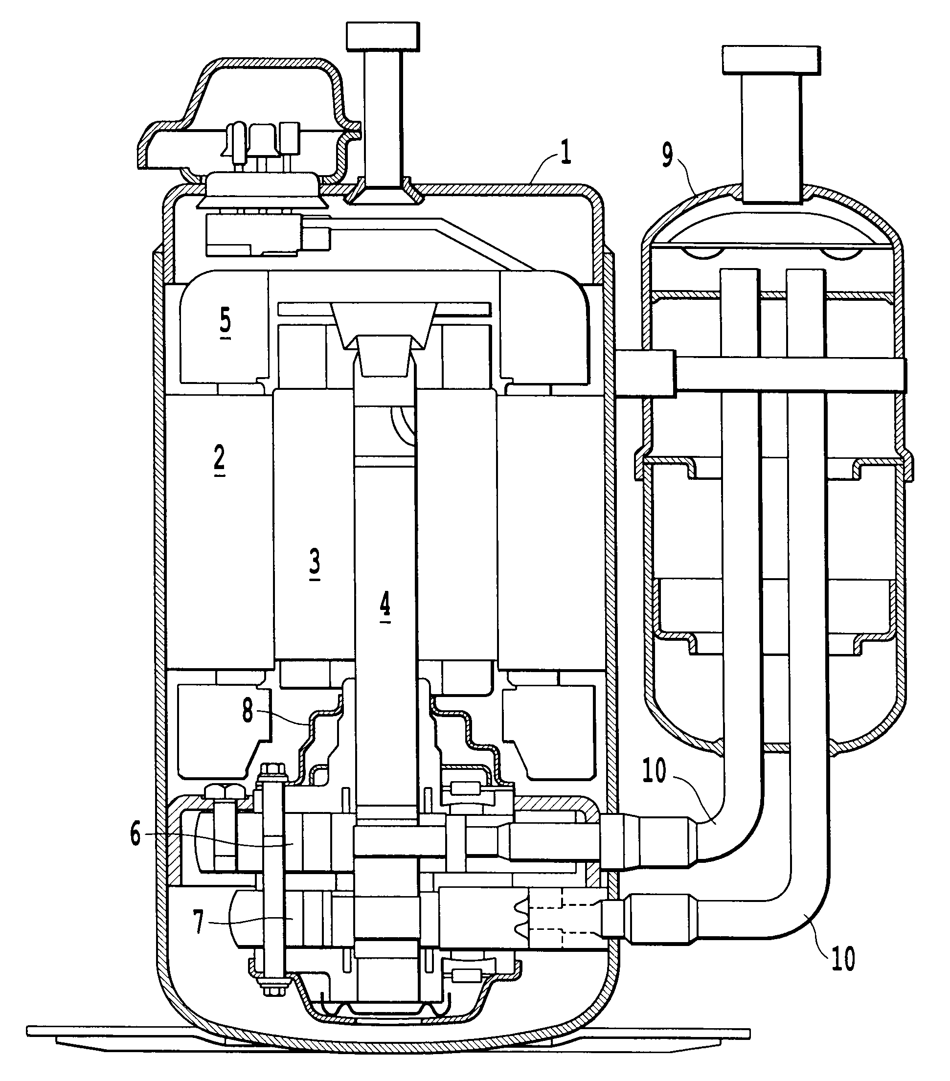
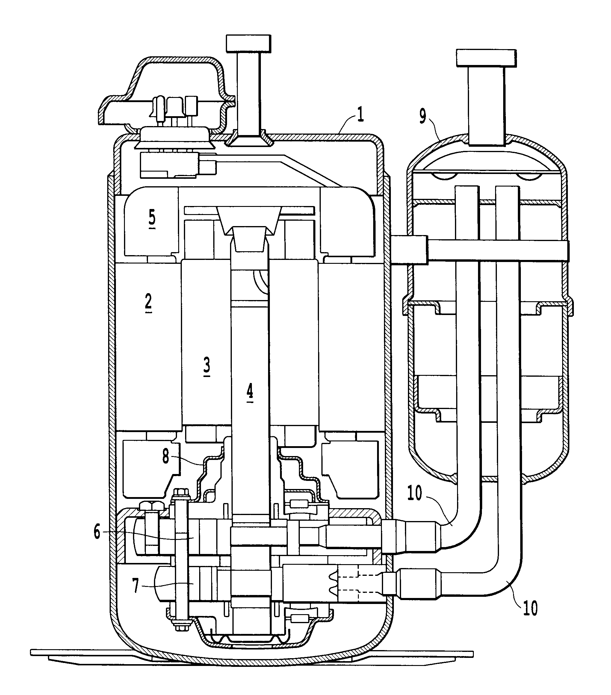
Image

Examples
preparation example 1
Catalyst Preparation Example 1
[0126]A2-liter autoclave made of SUS316L was fed with 6 g of a nickel diatomaceous earth catalyst (a product of Nikki Chemical Co., Ltd., N113) and 300 g of isooctane. The autoclave was purged with nitrogen and then purged with hydrogen, followed by increasing the temperature therein while the pressure of hydrogen was adjusted to 3.0 MPaG. After retaining the autoclave at 140° C. for 30 minutes, the autoclave was cooled to room temperature. The autoclave was purged with nitrogen and then fed with 10 g of acetaldehyde diethyl acetal. The autoclave was purged with nitrogen again and then purged with hydrogen, followed by increasing the temperature therein while the pressure of hydrogen was adjusted to 3.0 MPaG. After retaining the autoclave at 130° C. for 30 minutes, the autoclave was cooled to room temperature. A decrease in hydrogen pressure was confirmed as the reaction of acetaldehyde diethyl acetal proceeded while an increase in temperature allowed a...
production example 1
[0127]A 1-liter separable flask made of glass was fed with 60.5 g of isooctane, 30.0 g (2.50×10⁻¹ mol) of diethylene glycolmonomethyl ether, and 0.296 g of a boron trifluoride diethyl ether complex. Subsequently, 216.3 g (3.00 mol) of ethyl vinyl ether was added over 3 hours and 35 minutes. A reaction was exothermic, so a reaction solution was kept at 25° C. by placing the flask in an ice-water bath. After that, the reaction solution was transferred to a 1-liter separation funnel and washed with 50 ml of a 5% by mass aqueous solution of sodium hydroxide and then washed with 100 ml of distilled water six times, followed by removing the solvent and light components using a rotary evaporator under reduced pressure. Consequently, 235.1 g of a crude product was obtained.
[0128]The crude product had kinematic viscosities of 79.97 mm2 / s at 40° C. and 9.380 mm2 / s at 100° C.
[0129]Next, the autoclave containing the catalyst prepared in Catalyst Preparation Example 1 was opened and a liquid lay...
production example 2
[0132]A 1-liter separable flask made of glass was fed with 60.5 g of isooctane, 25.0 g (1.69×10⁻¹ mol) of dipropylene glycol monomethyl ether, and 0.200 g of a boron trifluoride diethyl ether complex. Subsequently, 133.8 g (1.86 mol) of ethyl vinyl ether was added over 3 hours.
[0133]After that, 151.8 g of a crude product was obtained by the same way as that of Production Example 1. The crude product had kinematic viscosities of 86.24 mm2 / s at 40° C. and 9.620 mm2 / s at 100° C.
[0134]Next, the autoclave containing the catalyst prepared in Catalyst Preparation Example 1 was opened and a liquid layer was then removed by decantation, followed by charging 300 g of isooctane and 100 g of the above-mentioned crude product. The autoclave was purged with nitrogen and then purged with hydrogen, followed by obtaining a base oil 2 by the same way as that of Production Example 1.
[0135]The yield thereof was 92.4 g. A theoretical structure of the base oil 2 estimated from the feed is (A) Ry=CH(CH3)C...
PUM
| Property | Measurement | Unit |
|---|---|---|
| molar ratio | aaaaa | aaaaa |
| viscosity index | aaaaa | aaaaa |
| temperature | aaaaa | aaaaa |
Abstract
Description
Claims
Application Information