Microdialysis catheter and process for manufacture

a microdialysis catheter and manufacturing process technology, applied in the field of microdialysis catheter manufacturing and to the microdialysis catheter, can solve the problems of high cost, high production cost, and inability to cover the canal structure with known membrane materials while maintaining the porous properties of the membrane, etc., to achieve the effect of short diffusion time of analyte and improved biocompatibility

Inactive Publication Date: 2009-02-26
ROCHE DIABETES CARE INC
View PDF6 Cites 9 Cited by
  • Summary
  • Abstract
  • Description
  • Claims
  • Application Information

AI Technical Summary

Benefits of technology

[0025]With a non-porous layer of the biocompatible material, substance transport (as with the underlying coating) occurs by diffusion. One aspect with a non-porous biocompatible layer is a short diffusion time of the analyte through the layer. The diffusion time is substantially influenced by the layer thickness. The biocompatible layer should therefore be applied as thinly as possible. The thickness of the biocompatible layer should preferably be between about 1 μm and about 10 μm. The covering layer to improve biocompatibility can for example be produced using 2-methacryloyloxyethyl phosphorylcholine polymer (MPC) which has no microscopic porosity.
[0026]Substance transport through a porous layer of the biocompatible material is generally based on diffusion of the analyte within an aqueous solution which wets the pores and usually also fills them. Consequently, the speed at which the analyte passes through the biocompatible layer is defined by a diffusion constant. For this reason, having a thin biocompatible layer is desirable for the speed of passage; its thickness can be between about 1 μm and about 10 μm. The fluid can thus pass through the porous layer relatively quickly and reach the coating which is diffusion-permeable to the analyte.

Problems solved by technology

Covering a canal structure with known membrane materials while maintaining the porous properties of the membrane is however difficult.
The addition of the supportive casing makes this known catheter resource-intensive and costly to manufacture, and it has to have a relatively large diameter since the membrane has to be inserted into the casing.
However, the spacers support only parts of the membrane and are not connected to the membrane or are connected to it only at a small number of places, so that many areas of the membrane are vulnerable to mechanical forces from outside.
With this solution too, the relatively large areas of the hollow-fiber membrane that are not directly connected with the reinforcing structure are vulnerable to mechanical forces from outside.

Method used


Image

  • Microdialysis catheter and process for manufacture
  • Microdialysis catheter and process for manufacture
  • Microdialysis catheter and process for manufacture

Examples


third embodiment

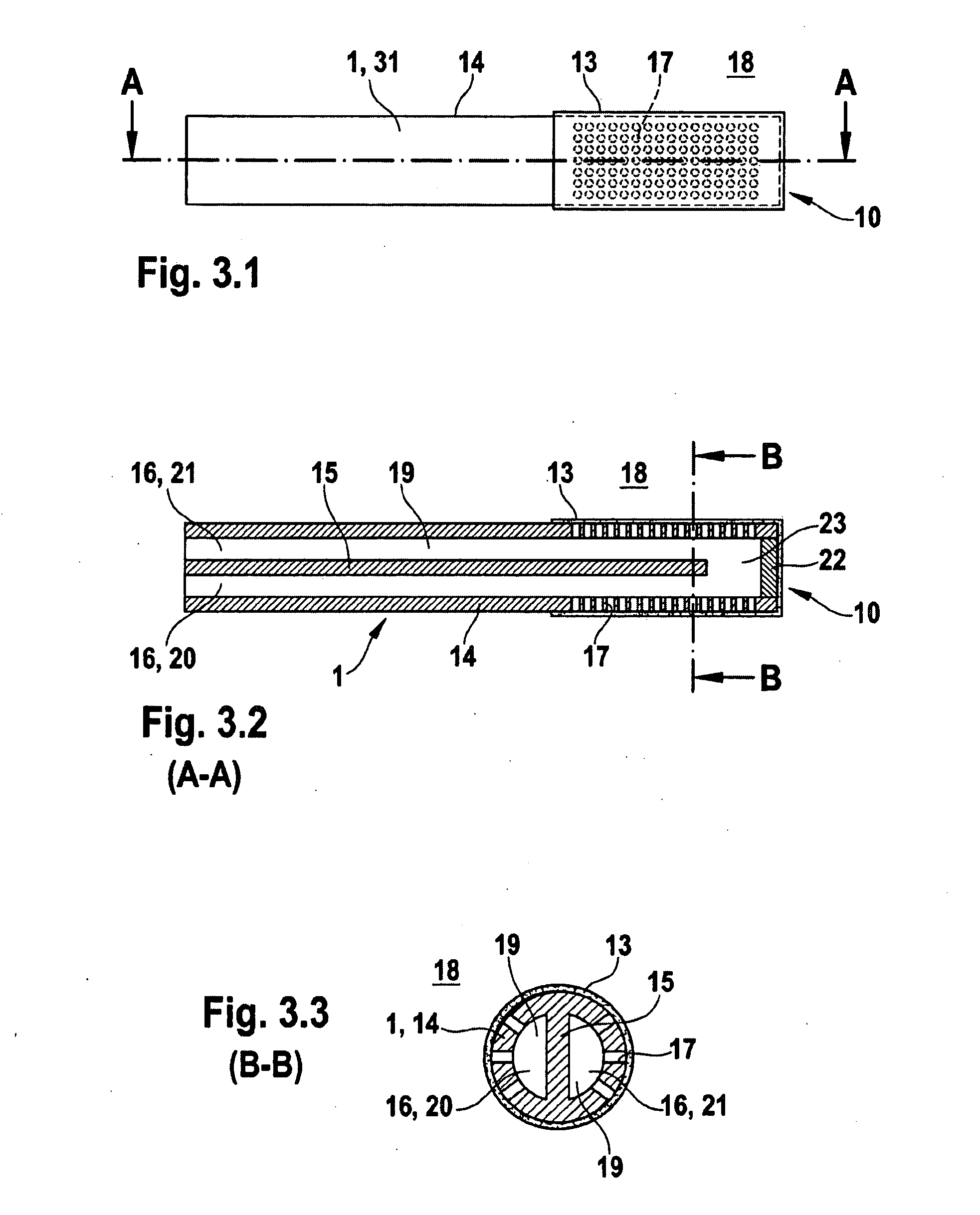
[0041]FIGS. 3.1 to 3.3 show schematically a microdialysis catheter according to an embodiment of the invention, with a carrier in the form of a multi-lumen tube.

[0042]One possible variant of a tubular carrier 1 with fluid channels is a multi-lumen tube 31. FIG. 3.1 shows a top view, FIG. 3.2 a longitudinal section (along A-A in FIG. 3.1) and FIG. 3.3 a transverse section (along B-B in FIG. 3.2) of an enlarged view of such a microdialysis catheter based on a multi-lumen tube.

[0043]The tubular outside wall 14 of the multi-lumen tube, i.e. a tube in which two lumina 16 with passage of fluid between them prevented by a dividing wall 15 are created, has side openings 17 in the area which, when the microdialysis catheter is in use, is inside the body, said openings allowing a connection for the passage of fluid to be made from the surrounding outer space 18 to the inner space 19 in the microdialysis catheter.

[0044]The dividing wall 15 between the two lumina 16 of the multi-lumen tube is, ...

fourth embodiment

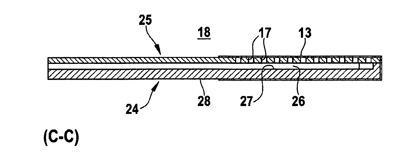
[0048]FIGS. 4.1 to 4.3 show schematically a microdialysis catheter according to an embodiment of the invention with a carrier in the form of a flat substrate with a cover.

[0049]According to another embodiment of the present invention, the carrier of the microdialysis catheter is a flat substrate with a cover. FIG. 4.1 shows a top view of the individual layers in such a microdialysis catheter, FIG. 4.2 a longitudinal section (along C-C in FIG. 4.1) and FIG. 4.3 a transverse section (along D-D in FIG. 4.1) through such a microdialysis catheter based on a flat substrate 24 with a cover 25. The sections are shown enlarged in FIGS. 4.2 and 4.3.

[0050]The flat substrate 24 contains as channel a canal structure 26 for supplying a perfusion fluid and for removing a dialysate. The canal structure 26 is bounded by an outer wall 29 and an inner ridge 30 and closed by the cover 25 of the flat substrate 24, where the cover 25 has a large number of openings 17 which are covered by a non-porous coa...


PUM

PropertyMeasurementUnit
diameteraaaaaaaaaa
areaaaaaaaaaaa
diameteraaaaaaaaaa

Abstract

A microdialysis catheter for partial implantation is used to supply a perfusion fluid and remove a dialysate, such as glucose, and comprises a carrier, at least one opening in the carrier, and a non-porous coating over the opening. The carrier contains at least one channel for supplying a perfusion fluid and for removing a dialysate and an area intended for implantation. The opening on the carrier has a connection with the channel for the passage of fluid. The non-porous coating is externally bonded to the carrier. The non-poroous coating is diffusion-permeable to an analyte and covers the area intended for implantation and the opening. A process for manufacturing the microdialysis catheter is also disclosed.

Description

REFERENCE[0001]This application is based on and claims priority to European Patent Application No. 07114968.6 filed Aug. 24, 2007, which is hereby incorporated by reference.FIELD[0002]The disclosure relates to a process for the manufacture of a microdialysis catheter and to a microdialysis catheter. Microdialysis catheters of this kind are generally known and are used to measure certain parameters within biological tissue (for example inside the human body) by means of microdialysis. An example of such a parameter is the level of blood glucose in subcutaneous tissue.BACKGROUND[0003]U.S. Pat. No. 6,572,566 B2 relates to a system for determining the concentration of at least one analyte in a bodily fluid. The system contains a canal with an exchange area via which substances can be taken up from the surrounding bodily fluid; it also has, downstream from the exchange area, a sensor with which the concentration of an analyte can be ascertained. The system has at least one integrated res...

Claims


Application Information

Patent Timeline
Patent Type & Authority Applications(United States)
IPC IPC(8): A61L29/16A61M25/00
CPCA61B5/14503A61B5/14528A61B5/14532A61B5/6852A61M25/007A61M25/0009A61M25/0045A61M25/0068A61B5/686
Inventor HOCHMUTH, GERNOTMISCHLER, REINHOLD
Owner ROCHE DIABETES CARE INC
Why Eureka
Try Eureka