
Biomass energy conversion apparatus and method

a technology of biomass energy and apparatus, which is applied in the direction of waste based fuel, combustible gas production, fuels, etc., can solve the problems of difficult to refine cellulosic materials in residuals into fuels, no generally useful or economic means, and pollutant into, so as to prevent soot formation, improve the efficiency and cost efficiency, and improve the effect of hydrogen-to-carbon monoxide ratio

Inactive Publication Date: 2009-03-26
RENEWABLE FUEL TECH
View PDF4 Cites 20 Cited by
  • Summary
  • Abstract
  • Description
  • Claims
  • Application Information

AI Technical Summary

Benefits of technology

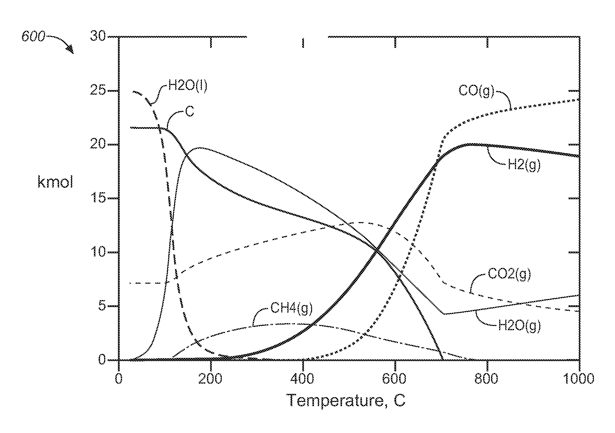
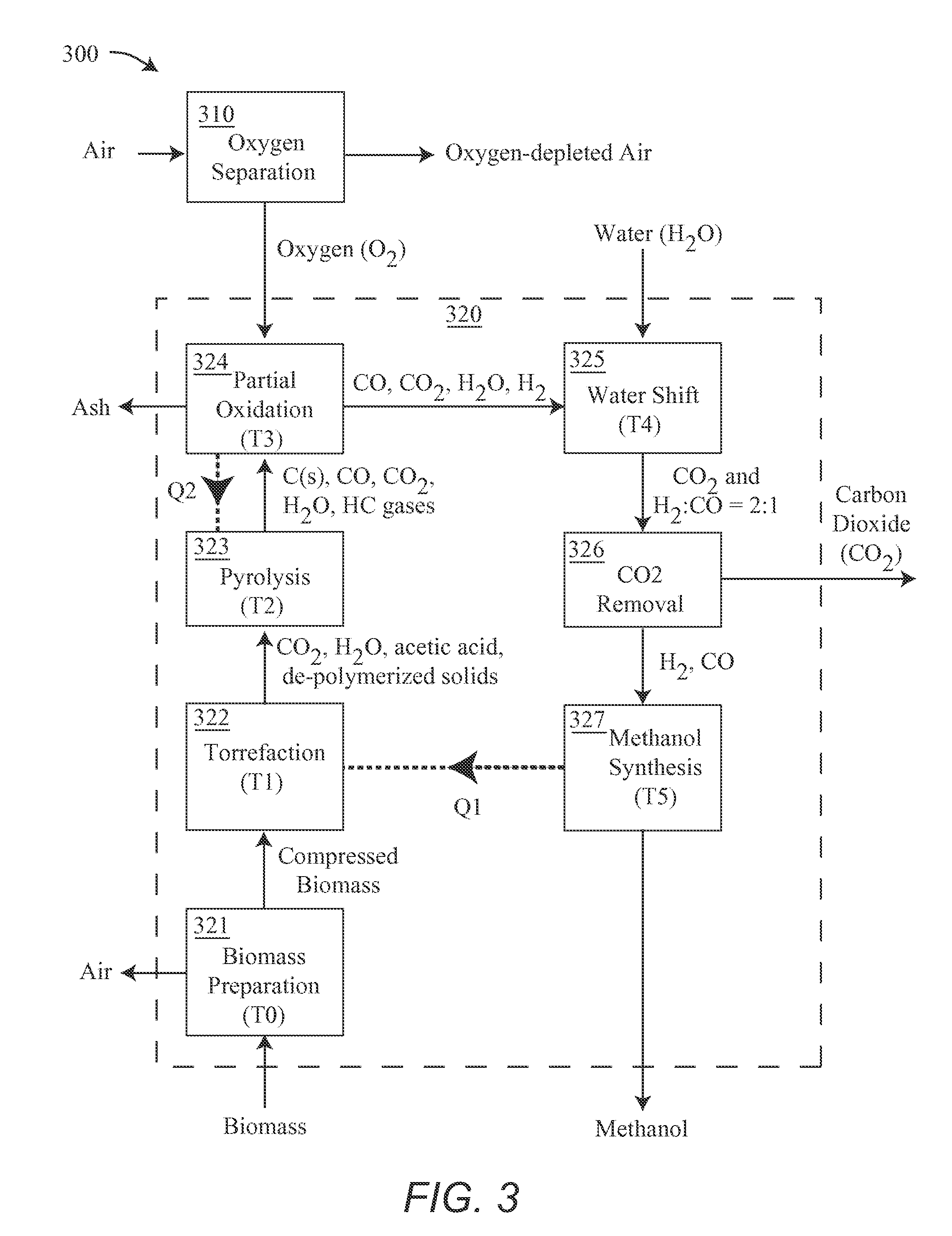
[0008]In certain embodiments, the disadvantages of prior art are overcome by a method or apparatus which may include one or more of the following features: 1) gasifying the feedstock sequentially at increasing temperatures; 2) forming process oxygen from ambient air; 3) reacting the feedstock with oxygen; 4) providing heat for feedstock gasification from a fuel synthesis process; 5) reacting the gasified feedstock with water to produce a favorable hydrogen-to-carbon monoxide ratio, and then removing the carbon dioxide and excess water to produce a mixture useful for a conversion to fuels; 6) combining the oxidizing gas with water and / or recirculating evolved gasses to achieve the proper stoichiometry for hydrogen rich synthesis gas; 7) producing an oxygen rich gas using surplus thermal energy from partial oxidation; 8) removing and sequestering or utilizing the carbon dioxide from the biomass; 9) a flash cooling step to prevent soot formation; 10) providing the heat required for air separation from a gas cooling process; and an efficient and cost effective method for disposal of agricultural waste.
[0013]Certain other embodiments of a biomass to fuel conversion system or process may include, but are not limited to, one or more of the following: 1) the production of oxygen; 2) energy recovery from the system to produce oxygen or nitrogen depleted air; 3) the use of oxygen, or nitrogen depleted air as the oxidizer; 4) the removal of trapped ambient nitrogen from the biomass; 5) effectively remove tars and other buildup from the system; 6) a system that facilitates sequestering or using the CO2 from the biomass; 7) utilizing several conversion steps, some of which are endothermic and some of which are exothermic, and efficiently using energy by transferring heat from exothermic to endothermic process steps; and 8) operating one of the conversion steps according to the following competing reactions by recirculating gases and / or adding water: a) C+CO2→2 CO; b) C+H2O→CO+H2; c) C+2 H2O→CO2+2H2; d) CO+H2O→CO2+H2; e) CH4+2H2O→CO2+4H2; 9) prevention of soot formation from the unwanted reverse reaction of 8a) 2CO→C+CO2.; 10) Mixing the oxidizer with steam and introducing this mixture as the oxidizer with the benefit of improved thermal uniformity in the partial oxidation reaction; 11) Mixing the oxidizer with steam and recirculated expressed hydrocarbon gasses, thus partially oxidizing these gases prior to introduction to the gassifier, resulting in improved thermal uniformity in the gassifier and improved synthesis gas composition; or 12) utilizing the ash content of the gasified biomass product as an inert, thermal transfer medium, and controlling the ash volume in the gassifier.
[0014]Advantages over the prior art may include, but are not limited to: a) integration of oxygen production from air with the system; 2) providing for carbon dioxide sequestration; 3) eliminating nitrogen and / or argon contamination from the system; 4) incorporation of a cleaning cycle; 5) providing a smaller scale process with good efficiency and economics; 6) increasing the carbon conversion efficiency and fuel output by effectively using heat generated in the process; 7) lowering the temperature required to achieve proper synthesis gas composition; 8) provide for opportunistic electrical generation; 9) provide process heat for general use, for instance in HVAC systems; 10) reducing the operating and maintenance costs; and 11) increasing the amount of biomass that may be processed and / or reducing the processing time.
[0017]In certain embodiments, the fuel is produced in conjunction with electricity. For instance, when fuel demand is low, electricity can be produced and sold. Alternatively, when consumer electricity demand is high, electrical production may have higher value. A real time electro-mechanical system to monitor and configure the optimum product mix reduces operating labor while optimizing the economic value. The carbon dioxide from the system may be used to enhance oil recover or otherwise be sequestered or utilized. In one embodiment, the relative output levels of fuel and electricity is monitored and the system is automatically configured to match the application needs.

Problems solved by technology

Many such materials are considered to be waste or are disposed of in a manner that poses environmental problems.
However, burning these residues releases CO2 and pollutants into the air, and is often prohibited.
While there is great interest in using crop residue for producing liquid fuels or power, there is as yet no generally useful or economic means for doing so.
One problem with utilizing crop residue, is that the cellulosic materials in the residuals are notoriously difficult to refine into fuels.
Thus, for example, many prior art reactors for converting biomass into fuels result in tar, ash, and soot.
Tar can negatively effect the performance of the conversion and the reactors, and generally must be removed before fuel synthesis.
In addition, other problems in converting biomass to fuels include the high energy input needed to produce synthesis gas of sufficient quality to be used for liquid fuel synthesis, and the high capital cost associated with production of O2 gas, if it is to be used in the process.

Method used


Image

  • Biomass energy conversion apparatus and method
  • Biomass energy conversion apparatus and method
  • Biomass energy conversion apparatus and method

Examples


first embodiment

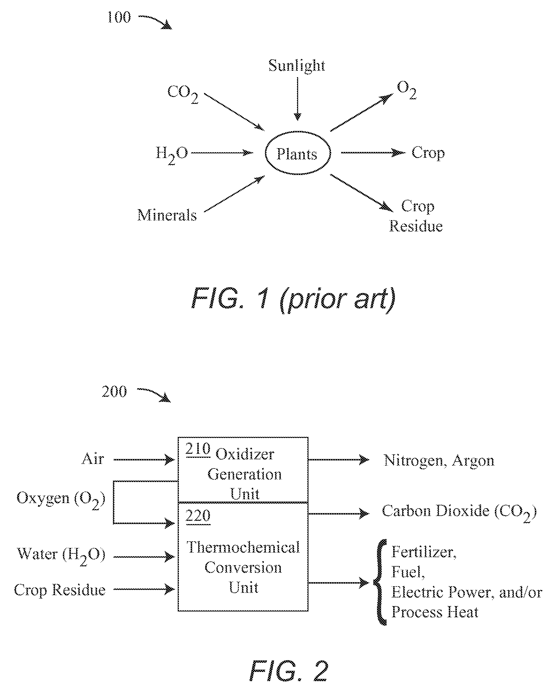
[0030]FIG. 2 is a schematic of a first embodiment biomass energy conversion apparatus 200. Apparatus 200 includes an oxygen production unit 210 and a thermochemical conversion unit 220. Also shown in FIG. 2 is the flow of air, water, and crop residue into apparatus 200, and the flow of nitrogen, argon, a fuel, carbon dioxide, and fertilizer from apparatus 200. Although FIG. 2 shows oxygen production unit 210 and thermochemical conversion unit 220, in certain embodiments, portions of the units are integrated or shared.

[0031]Biomass energy conversion apparatus 200 may work in conjunction with prior art agricultural process 100 to convert agricultural crop residue into useful products including, but not limited to, one or more of a fuel, electric power, fertilizer, or process heat. The fuel may be, for example and without limitation, a liquid fuel, such as methanol or dimethyl ether. In addition, apparatus 200 may also produce concentrated streams of nitrogen and / or carbon dioxide, whi...

second embodiment

[0054]FIG. 4 is a schematic of a process 400 for a biomass energy conversion apparatus which may be, for example and without limitation, biomass energy conversion apparatus 200. Process 400 is generally similar to process 300, except as explicitly discussed below.

[0055]In process 400, oxygen from oxygen separation process 310 is provided to partial oxidation process 324 and a pyrolysis process 423. The energy to drive the pyrolysis reactions in pyrolysis process 323, which was, for example supplied by Q2 in processes 300, is supplied by exothermic reactions between oxygen and the other gases entering the pyrolysis. Thus, for example, the equipment to carry out pyrolysis process 432 includes a burner to combust oxygen to increase the temperature of the pyrolysis process to a value of T2.

[0056]Also in process 400, heat in the amount of Q3 is provided from partial oxidation process 324 to a thermal electric generator 401, which powers oxygen separation process 310. Some of the power fr...

third embodiment

[0057]FIG. 5 is a schematic of a process 500 for a biomass energy conversion apparatus which may be, for example and without limitation, biomass energy conversion apparatus 200. Process 500 is generally similar to processes 300 and / or 400, and includes a thermochemical conversion process 520 which is generally similar to processes 320, except as explicitly discussed below. Specifically, process 500 has components that may be configured to achieve different outputs from a biomass stream and in which electricity is chosen as the primary output.

[0058]Process 520 includes an electric generator 501, heat exchange processes 503 and 505, a condenser process 507 and a compression process 509. Process 520 converts biomass into electricity in electric generator 501, which requires an energy rich stream that does not have to have the specific concentrations required of a fuel synthesis reaction. Process 520 therefore does not require a water shift process to obtain specific molar ratios, as do...


PUM

PropertyMeasurementUnit
electricaaaaaaaaaa
heataaaaaaaaaa
electric poweraaaaaaaaaa

Abstract

Method and apparatus are disclosed to utilize the energy in biomass (waste agricultural products). The inventive method and apparatus utilized heat and mass flow to efficiently generate a variety of products from biomass. In various embodiment, the invention may generate a liquid fuel (such as methanol or dimethyl ether), pure liquid CO2 (intended for CO2 sequestration), a soil enhancement product (intended to return to the agricultural site), process heat, and / or electricity. In one embodiment, the process requires no external energy inputs, and preserves a large percentage (ie. >50%) of the energy contained in the biomass. In another embodiment, the inventive method and apparatus can selectively be operated to produce electricity and or liquid fuels.

Description

CROSS-REFERENCE TO RELATED APPLICATIONS[0001]This application claims the benefit of U.S. Provisional Application No. 60 / 952,506, filed Jul. 27, 2007, the entire contents of which are hereby incorporated by reference herein and made part of this specification.BACKGROUND OF THE INVENTION[0002]1. Field of the Invention[0003]The present invention generally relates to the utilization of energy from biomass, and more particularly to a method and system that is capable of converting crop residues into one or more of a liquid fuel, electrical power or process heat.[0004]2. Discussion of the Background[0005]The prospect of converting biomass in the form of agricultural products and / or waste into fuels or energy is appealing, and is seen as a possible route to energy independence. Many such materials are considered to be waste or are disposed of in a manner that poses environmental problems. One such practice is the burning of agricultural waste, such as crop residues, in the field. Since the...

Claims


Application Information

Patent Timeline
Patent Type & Authority Applications(United States)
IPC IPC(8): C10J3/00
CPCC10J3/00Y02E50/30C10J2300/0903C10J2300/0916C10J2300/0959C10J2300/1665C10J2300/1671C10J2300/1678C10J2300/1846C10L5/44C10L9/083Y02E20/185Y02E50/10Y02E50/15Y02E50/18Y02E50/32Y02E20/18C10J3/66
Inventor SHULENBERGER, ARTHUR M.WECHSLER, MARK
Owner RENEWABLE FUEL TECH
Learn More