Micromachined electrolyte sheet, fuel cell devices utilizing such, and micromachining method for making fuel cell devices

Inactive Publication Date: 2009-03-26
CORNING INC
View PDF12 Cites 54 Cited by
  • Summary
  • Abstract
  • Description
  • Claims
  • Application Information

AI Technical Summary

Benefits of technology

[0017]One advantage of the present invention is that it advantageously allows fabrication of new fuel cell designs, and/or advantageously increases the fabrication yield and strength of the current fuel cell devices. More specifically, the speed, placement accuracy, and resulting quality of the electrolyte sheet edge(s) enable flexibility in device design, handling, and improved electrolyte sheet edge strength. Preferably, the surface roughness of the laser micromachined regions is less than 0.5 μm RMS, more preferably less than 0.4 μm RMS. Preferably this surface exhibits peak-to-valley roughness of less than 5.5 μm, or Ra surface roughness of less than 0.3 μm. Fuel Cell devices can also be drilled, cut, or micromachined at various times during the fabrication process resulting in fuel cell devices with unique attributes such as complex perimeter shapes or via hole patterns, electrodes or other layers existing up to the electrolyte edge, and thin electrolyte areas less than 5 μm thick. This micromachining process can be utilized at any desired time after the electrolyte sintering, enabling flexibility in device fabrication. The resulting method adva

Problems solved by technology

Mechanically punching and cutting of the un-fired electrolyte puts limitations on the fabrication speed, feature size, wrinkle, and edge quality produced.
Such prediction is very difficult to do with the desired accuracy and require actual devices to be sacrificed for testing.
Thin (less than 50 μm) zirconia based sintered electrolyte sheets are brittle when they are either cut or/and drilled by mechanical means, due to crack formation.
Applicants attempted to utilize CO2 laser in drilling thin zirconia c

Method used


Image

  • Micromachined electrolyte sheet, fuel cell devices utilizing such, and micromachining method for making fuel cell devices
  • Micromachined electrolyte sheet, fuel cell devices utilizing such, and micromachining method for making fuel cell devices
  • Micromachined electrolyte sheet, fuel cell devices utilizing such, and micromachining method for making fuel cell devices

Examples


example 1a

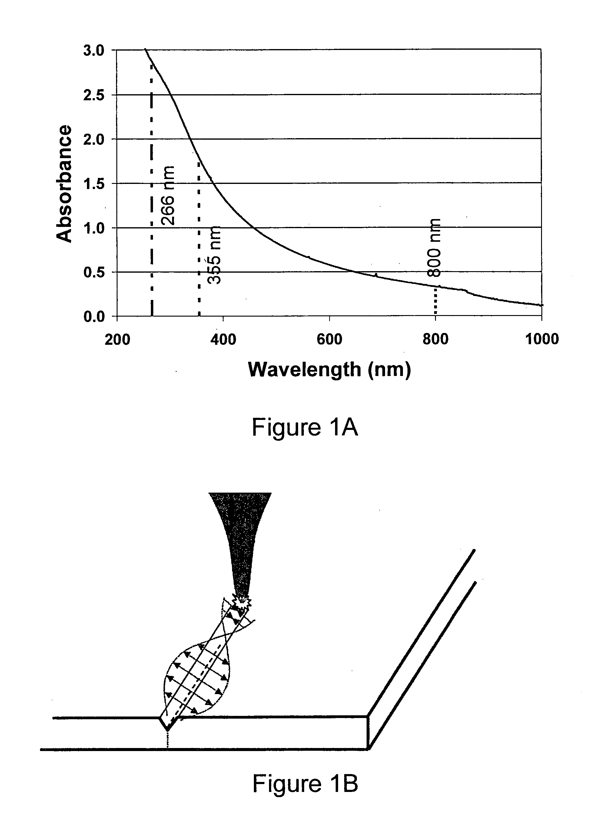
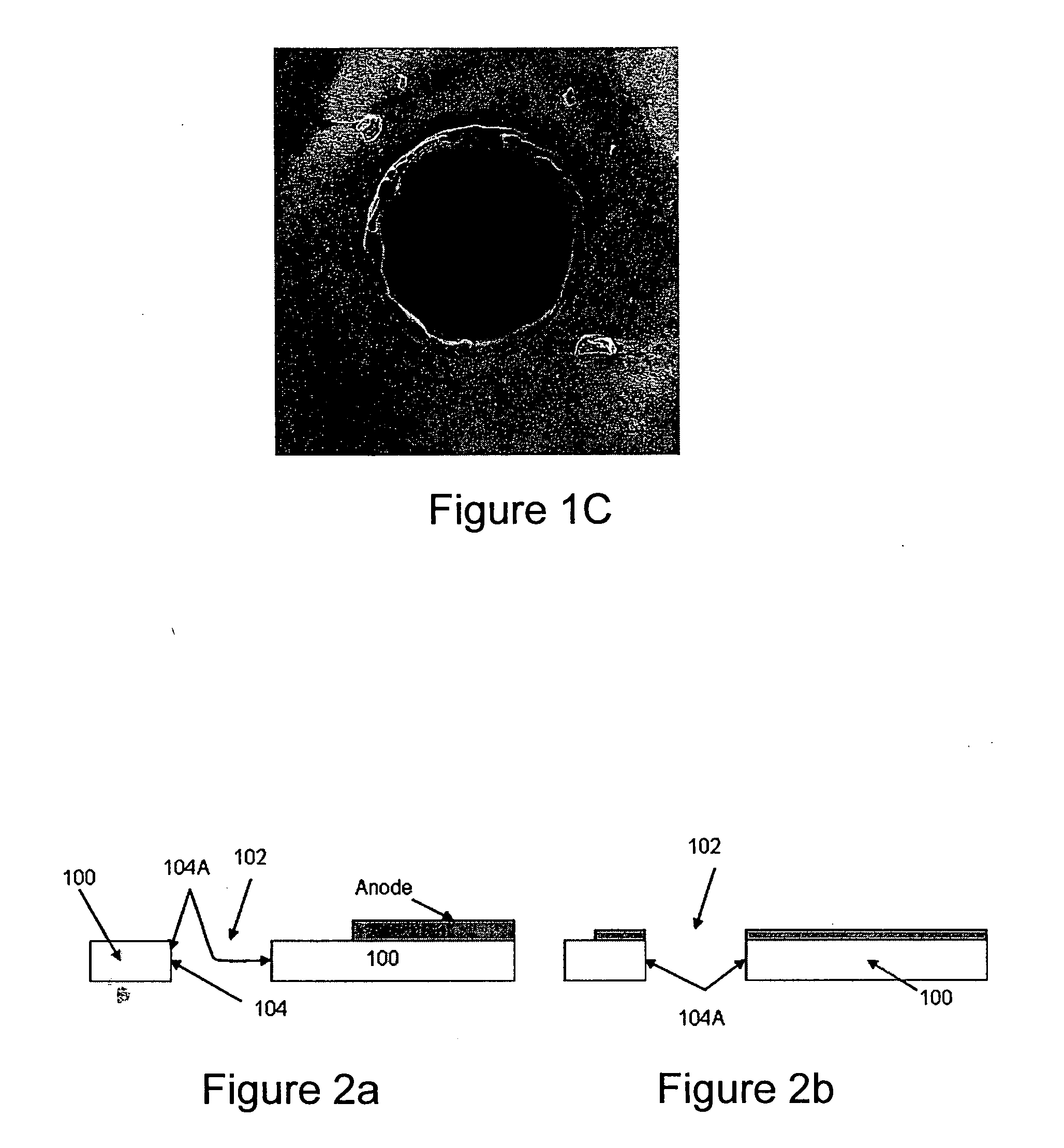
[0081]A plano-convex (PCX) lens L1 with a focal length of 10 cm was used to focus the light in proximity to the zirconia based electrolyte sheet. A simple percussion drilling technique was used. The 266 nm laser 160 had its optical power level set at 340 mW. This power level corresponds to 340 μJ per pulse. Since the diameter of the via hole of this example is about 50 μm, this gives a laser fluence level of roughly 17 J / cm2. In the experiment the hole was laser cut / drilled through the electrolyte sheet after less than 2000 pulses or 2 seconds. The minimum fluence level required to observe laser ablation effects (i.e. ablation threshold level) was less than 6 J / cm2, e.g., about 1 (0.9 to 1.1 J / cm2). The via shape produced is influenced by the laser beam shape. Laser micromachining, without generating microcracks, was also achieved using a range power levels of 100 to 600 μJ per pulse, and fluence levels of 5 to 30 J / cm2.

[0082]FIG. 6a and FIG. 6b are photographs taken with an optical...

example 1b

[0083]FIGS. 7a and 7b are SEM images of straight edges laser micromachined with the above described laser cutting equipment and at the same settings, using a cut speed of 1 mm / s. Cutting speeds of 0.5 to 2 mm / s can be utilized, but the cutting speed was ultimately limited by the laser repetition rate (i.e., max. speed is less than spot size diameter×repetition rate). More specifically, FIG. 7a shows a top view of the laser micromachined edge surface and FIG. 7b shows a side view of the micromachined edge surface. Redeposition 108 is seen as a discolored band near the micromachined edge on the laser incident side is also apparent (see FIG. 7a).

Examples Using ns Laser Configuration #2

examples 2 to 4f

[0084]In another embodiment of a laser micromachining system for (nanosecond) laser cutting of sintered zirconia based electrolyte sheet, a frequency-quadrupled Nd:YVO4 laser, made by Spectra-Physics (HIPPO-266QW), was utilized (Examples 2-3B). The output wavelength of this exemplary laser is 266 nm. The ns laser 160, running at a repetition rate of 30 to 120 kHz, has a peak laser power of approximately 2.5 W and a pulse duration of less than 15 ns according to the specifications from the manufacturer. A 3× optical beam expander (BE) and with a 10.3 cm focal length telecentric lens L1 were used in conjunction with the laser 160 to cut the electrolyte sheet 100. (FIG. 8). Single pulse ablation on electrolyte test samples showed that the focal spot size of the laser beam (beam waist) is about 20 μm in diameter.


PUM

PropertyMeasurementUnit
Grain sizeaaaaaaaaaa
Lengthaaaaaaaaaa

Abstract

A sintered electrolyte sheet comprising: a body of no more than 45 μm thick and laser machined features with at least one edge surface having at least 10% ablation. A method of micromachining the electrolyte sheet includes the steps of: (i) supporting a sintered electrolyte sheet; (ii) micromachining said sheet with a laser, wherein said laser has a wavelength of less than 2 μm, fluence of less than 200 Joules/cm2, repetition rate (RR) of between 30 Hz and 1 MHz, and cutting speed of preferably over 30 mm/sec.

Description

BACKGROUND OF THE INVENTION[0001]1. Field of the Invention[0002]This invention relates in general to ceramic electrolytes and fuel cell devices utilizing them, and to the laser micromachining of electrolyte sheets and electrolyte supported multi-cell solid oxide fuel cell devices.[0003]2. Technical Background[0004]The present invention pertains to articles formed by laser processing of solid oxide fuel cell electrolyte sheets, as well as manufacture of electrolyte supported solid oxide fuel cells and fuel cell devices.[0005]Solid oxide fuel cell devices incorporating flexible ceramic electrolyte sheets are known. In such fuel cell devices, often one or more electrolyte sheets are supported within a housing, on a frame, or between a pair of mounting assemblies, which might be either a frame or a manifold. The electrolyte sheets may be utilized either in a multi-cell or single cell design.[0006]A common approach utilizes a fuel cell device that consists of a single cell design where t...

Claims


Application Information

Patent Timeline
IPC IPC(8): H01M8/10C23F4/00
CPCB23K26/408H01M8/122H01M8/1246Y02E60/525H01M2008/1293Y02E60/521H01M8/1253B23K26/40B23K2103/52Y02E60/50Y02P70/50
Inventor BLANCHARD, WILLIAM CORTEZGARNER, SEAN MATTHEWKETCHAM, THOMAS DALELI, XINGHUA
Owner CORNING INC
Why Eureka
Try Eureka