Pore Diffusion Type Flat Membrane Separating Apparatus, Flat Membrane Concentrating Apparatus, Regenerated Cellulose Porous Membrane for Pore Diffusion, and Method of Non-Destructive Inspection of Flat Membrane

a technology of pore diffusion and separating apparatus, which is applied in the field of porous membranes, can solve the problems of inability to fully realize the effect of pore diffusion, reduce the influence of interfacial change of membranes, and facilitate the regeneration of membranes

Inactive Publication Date: 2009-06-11
MANABE SEI ICHI
View PDF4 Cites 42 Cited by
  • Summary
  • Abstract
  • Description
  • Claims
  • Application Information

AI Technical Summary

Benefits of technology

[0088]The first object of the present invention relates to a pore diffusion type flat membrane separation apparatus, the object being to provide inexpensively the pore diffusion type flat membrane separation apparatus which uses, as the solid-liquid separating method, not filtration requiring application of transmembrane pressure difference, but pore diffusion, thereby to relieve pore clogging of the membrane and which also allows reuse of the membrane.
[0089]The second object of the present invention relates to a flat membrane concentration apparatus capable of solving concentration reduction in the target substance whish is a shortcoming of the pore diffusion technique, the object being to provide a flat membrane concentration apparatus which provides a function of concentrating a particular component in a solution and which is light-weight and of a simple construction, thus being readily handled. More particularly, the object is to provide a concentrating apparatus whose membrane housing is reusable, having the features of (a) increase of collection ratio of concentrated component, (b) minimization of osmotic pressure during concentration, (c) weight reduction, (d) capability of an intermediate molecular weight component having a molecular weight of 1000 or more, (e) ability of continuous concentration, and (f) sanitary property.

Problems solved by technology

Further, with these modules, for retention of the membrane, a portion of the membrane and a support are adhesively bonded to each other by means of a resin or the like, Especially, when its effective filtering area exceeds 0.1 m2, the vessel (housing) or the support needs to be formed of stainless steel in order to withstand an transmembrane pressure difference, so that the mode tends to be hardly portable or tends to be configured as a hollow fiber module having a portion of the membrane being adhesively fixed by means of a resin or the like.
As this pressure is born mainly by the outermost layer of the module in the case of the flat membrane module, its outermost layer is added with a reinforcing material, which addition makes observation inside the module difficult.
Also, in the case of the membrane filter technique, clogging of the pores inside the membrane occurs, which makes regeneration of the membrane difficult.
Further, as the separation by the membrane filter technique relies on the pore diameter of the membrane, if the size of the molecules to be separated is small, the average pore diameter of the separating membrane too needs to be small correspondingly, so that the filtering amount per effective filtering area becomes correspondingly small thus becoming even more liable to invite the clogging phenomenon.
Notwithstanding the above, in the case of the above module having adhesive bonding with resin, as a portion of the membrane and the support are adhesively bonded with each other for retention of the membrane, if the membrane or the module portion alone has been damaged, replacement of such damaged portion alone was difficult.
Further, in the case of the module using the membrane filter technique, in effecting filtering separation, due to the readiness of clogging in the membrane, it is difficult to maintain stable membrane filtering performance.
As a result, its manufacturing costs would be high.
Moisture elimination relying on evaporation or concentration does not involve any phase separation and also consumes a great amount of energy.
Further, this concentration results in loss of activity of a biologically active agent such as a protein.
The precipitation method provides selective concentration, but involves dilution through desorption and requires high costs.
However, with such increase of transmembrane pressure difference, there occurs concentration of polymer component on the membrane surface, which leads to reduction in the filtration rate and reduction in the collection ratio.
Such device or arrangement for solving these problems relating to pressure resistance and membrane charge density often comprises a complicated and large structural feature of the apparatus, and a metallic material is generally employed as the material for forming the support.
Hence, in the module of the apparatus, the respective members constituting the same are formed integral or have shapes which cannot be disassembled easily, so that the transportation, installment, cleaning of the support or liquid inlet / outlet connectors, replacement of expendable parts or the membrane would be difficult.
For this reason, commercial application of a concentrating apparatus using flat membrane has been believed impossible.
In this, however, if the stock solution contains diffused substance at a high concentration, this diffused substance will be precipitated in the lower layer, thus leading to disadvantageous reduction in the effective filtering area of the membrane.
And, as a problem commonly suffered by the membrane concentration technique, with increase in the concentration ratio during membrane concentration, there occurs increase in the osmotic pressure, so that the concentration speed will be reduced, and filtering-out of component to be collected occurs in the filtered liquid also.
Whereas, as there exist almost no pores of diameters which allow passage therethrough of the viruses or prions having larger diameters than albumin, it takes a long time for their passage through the pores.
In the case of the 
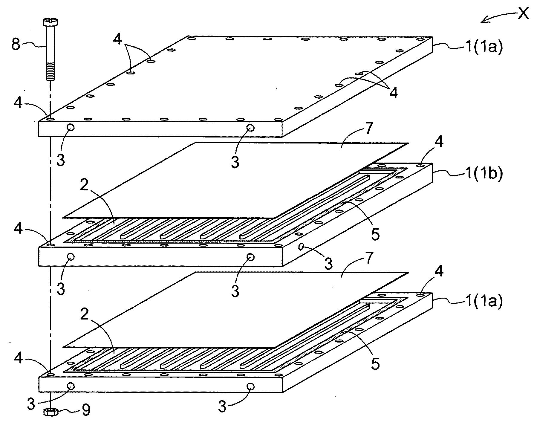
hollow fiber membrane, the support for membrane is not needed, but as the vessel and the hollow fibers are formed integral as the membrane separator, replacement of the membrane alone is not possible, so that the entire vessel needs to be replaced.
On the other hand, in the case of the flat membrane, the support for supporting the membrane is needed, so that there is the problem of enlargement of the module per unit membrane area and enlargement in the filling liquid amount.
With this method, the phase separation requires long time, so that it has been industrially difficult to obtain the membrane thickness of 200 μm or more and the porosity of 80% or more.
And, it has been difficult also to obtain the average pore diameter of 10 nm or less.
With this method, however, there occurs severance of main chain, leading to significant reduction in mechanical strength.
So, it has been difficult to apply this method to a porous membrane having a large porosity in particular.
Further, since there occurs also a change in the pore characteristics due to the saponification treatment, there is known no practical application of regenerated cellulose membrane by combination of the micro-phase separation technique and saponification treatment.
As a result, the membrane separation apparatus will be heavy and not handy and will be costly as well.
In the case of elimination associated with affinity, e.g. the adsorption mechanism, it is not possible to anticipate its eliminating effect for an unknown infectious substance.
However, with reduction in the average pore diameter, not only the treating speed is decreased, but also clogging is more likely to occur, in the case of filtration.
This relationship, however, has not yet been elucidated.
However, increase of porosity (Pr) leads to deterioration in the dynamic characteristics of the membrane.
However, no method has been proposed yet which enables a porosity (Pr) of 0.7 or more with maintaining the average pore diameter small.
This treatment can cause a change in the configuration of the membrane.
However, if such configuration change is isotropic and this change is minor, the designing of membrane module will become easy.
Even if there existed a membrane manufacturing method which allows setting the average pore diameter as small as 10 nm or less, the membrane thickness as large as 200 μm or more and the porosity (Pr) as large as 0.8 or more and which allows also rendering the development degree of intermolecular hydrogen bond in a multi-layered, regenerated cellulose flat membrane 40% or less, such method would suffer from limited filtering treatment amount and significantly increased membrane treatment cost, hence being not put into actual use.
If these microparticles are mixed in a final product, they can cause various infectious diseases and fever.
In the case of inspection by this method, however, as the gold colloidal particles remain within the membrane after the inspection, the membrane after the inspection is not reusable.
As it is almost impossible to completely eliminate gold within the pores, in actuality, the membrane after the testing is disposed of as a waste.
That is, this method, as an inspection, is a destructive inspection.
In the determination of gold particle concentration using a spectroscope, as determination of eliminating ability, there is provided representation in terms of logarithmic particle removal factor of 3 (the ratio between the concentration in the stock solution and the concentration in the treatment liquid is 1000), so the ability test by the direct method suffers the problem of insufficient precision.
Therefore, there is the problem that prior to effecting the integrity test, the used membrane needs to be cleaned with using e.g. caustic soda.
On the other hand, in the case of the indirect method in the integrity test, the microparticle eliminating ability of the membrane is not directly determined.
Moreover, in this method, the particle characteristics are not directly observed.
Further, in the case of a fluid having a large interfacial tension, such fluid applies a large negative pressure to the membrane, so that the pores thereof may be dynamically deformed or even destroyed by the integrity test.
Therefore, depending on the kinds of liquid employed, it often happens that the method becomes a destructive testing method.
Firstly, in the direct method, the microparticles employed are colloidal particles of gold, which particles are highly reactive with proteins.
And, if these substances remain within the membrane, this will result in change in the entrapping ability for the gold colloidal particles within the pores.
As this is a destructive test, the test is conducted as a random inspection.
And, there even exists a tendency of prohibiting reuse especially among the membrane manufacturers as the suppliers of the membranes.
As described above, reuse of membrane has been believed to be impossible in the field of microparticle elimination.
As causes for this, (1), the microparticle eliminating ability of membrane once used, is not known and most of the integrity tests are a destructive test; (2) it is almost impossible to completely eliminate the substance remaining within the membrane after its use and the elimination cannot be quantified; and (3) process validation including regeneration step of membrane is difficult.

Method used


Image

  • Pore Diffusion Type Flat Membrane Separating Apparatus, Flat Membrane Concentrating Apparatus, Regenerated Cellulose Porous Membrane for Pore Diffusion, and Method of Non-Destructive Inspection of Flat Membrane
  • Pore Diffusion Type Flat Membrane Separating Apparatus, Flat Membrane Concentrating Apparatus, Regenerated Cellulose Porous Membrane for Pore Diffusion, and Method of Non-Destructive Inspection of Flat Membrane
  • Pore Diffusion Type Flat Membrane Separating Apparatus, Flat Membrane Concentrating Apparatus, Regenerated Cellulose Porous Membrane for Pore Diffusion, and Method of Non-Destructive Inspection of Flat Membrane

Examples


example 1

[0228]A flat plate-like support 1 formed of a polycarbonate plate (referred to as “support” hereinafter) is formed like a flat plate having a plate thickness of about 0.6 cm, a length of 40 cm and a width of 50 cm. And, in one or both faces thereof, there is formed a concave flow conduit 2 having a width of about 1.5 cm and a depth of 0.1 cm, the conduit 2 being in communication with a water conduit 3 from its inlet 3a to its outlet 3b.

[0229]The water conduit 3 functions as entrance / exit for the treatment liquid. In a lateral face of the support 1, there are formed holes having a diameter of about 0.4 cm from the leading end to the terminal end of the flow conduit 2 to be continuous therewith. This ensures flow of the treated liquid along a predetermined direction.

[0230]The thread holes 4 are formed with an inter-hole spacing of 5 cm. And, these are formed directly in the support 1. Then, screws 8 are inserted into them to fix the support 1. The screws 8 need not provide the fixati...

example 2

[0250]FIG. 4 is a view schematically showing a flat membrane concentration apparatus Y. The flat membrane concentration apparatus Y comprises an alternatively superposed assembly of supports 1 and flat membranes 7. The atmospheric pressure is applied to the outer support 1a, thus increasing the close contact between the supports and increasing the packing effect.

[0251]FIG. 5 is a schematic vertical section of the flat membrane concentration apparatus Y. The dot line shown represents omission of a plurality of supports and flat members bound between, from the illustration. In this, a space 10 between the outer disposed support 1a and the flat membrane 7 is under a depressurized condition whereas a space 11 is under a pressurized condition. The support on the pressurized side too defines a flow conduit, which flow conduit facilitates collection of concentrated liquid and allows reverse washing, if necessary.

[0252]As to the support 1b and flat member 7 disposed intermediate in FIG. 5, ...

example 3

[0279]Degassing and filtration were carried out for a solution in which cellulose acetate (average polymerization degree 210) having an average substitution degree of 2.50 was dissolved in a weight concentration (weight concentration in the flow casting stock solution) of 11.5% and a solution prepared with acetone: 51.6% in weight, methanol: 6.5% in weight, CaCl2.2H2O: 1.2% in weight, cyclohexanol: 29.2% in weight, respectively.

[0280]Flow casting was effected on the glass plate to a flow casting thickness of 1 mm. Then, this was kept at 25° C. for 30 minutes to allow a micro-phase separation to occur. Thereafter, this was submerged together with the glass plate in methanol at 25° C., to stop further progress of the micro-phase separation. Then, components remaining in the membrane after the phase separation were eliminated by washing with purified water. This was submerged in 25° C. water adjusted to pH=12.0 with caustic soda to allow a saponification reaction to take place.

[0281]Th...


PUM

PropertyMeasurementUnit
pore diameteraaaaaaaaaa
thicknessaaaaaaaaaa

Abstract

A pore diffusion type flat membrane separation apparatus X including a plurality of flat membranes 7 and a plurality of flat plate-like supports 1 arranged alternately with each other, each flat membrane 7 defining a plurality of pores and configured to separate a predetermined dispersed substance contained in a solution by a pore diffusion technique, each flat plate-like support 1 having a flow conduit 2 on one or both faces thereof. A ratio between a spatial volume of the flow conduit 2 and a membrane area of the flat membrane 7 is set from 0.04 to 0.4 cm. The flat plate-like support 1 includes, in at least two positions in a lateral face thereof water conduits 3 in communication with the flow conduit 2, so that flow directions of the solution in the flow conduits 2 of upper and lower flat plate-like supports 1 across the flat membrane 7 may be substantially same directions. The flat plate-like support 1 and the flat membrane 7 can be assembled with and disassembled from each other.

Description

TECHNICAL FIELD[0001]The present invention relates to a pore diffusion type flat membrane separation apparatus for effecting solid-liquid separation through utilization of a pore diffusion mechanism of a flat membrane. The invention relates also to a flat membrane concentration apparatus using a flat membrane, a regenerated cellulose porous membrane as a flat membrane, and to a method of inspecting a flat membrane.BACKGROUND ARTPore Diffusion Type Flat Membrane Separation Apparatus[0002]Examples of the conventional membrane separation apparatuses for liquid separation include a hollow fiber membrane module, a tubular membrane module, a flat membrane module, a spiral membrane module, a pleated membrane module, and so on, all of which rely mainly on filtration separation technique. Further, with these modules, for retention of the membrane, a portion of the membrane and a support are adhesively bonded to each other by means of a resin or the like, Especially, when its effective filter...

Claims


Application Information

Patent Timeline
Patent Type & Authority Applications(United States)
IPC IPC(8): B01D63/08B01D69/10C08B16/00G01M19/00G01M99/00
CPCB01D63/082G01N15/08B01D67/0009B01D67/0093B01D71/10B01D71/14B01D65/102B01D2313/20B01D2313/086B01D2325/36B01D2325/02B01D2323/08C08L1/12C08L1/10B01D63/085B01D61/28B01D61/362B01D69/06C08K3/16C08K3/24
Inventor MANABE, SEI-ICHIHANADA, SAORISEKI, CHIEKOOTSUBO, KEIKO
Owner MANABE SEI ICHI
Why Eureka
Try Eureka