Ion-beam source

a beam source and beam technology, applied in the direction of electric discharge tubes, instruments, measurement devices, etc., can solve the problems of high rf voltage (a few kv) between the terminals, insufficient plasma density for obtaining high ion current densities, and inability to provide high density plasma, etc., to achieve high coupling to plasma, high degree of uniformity, and high efficiency of plasma production

Active Publication Date: 2009-07-30
GODYAK VALERY
View PDF34 Cites 31 Cited by
  • Summary
  • Abstract
  • Description
  • Claims
  • Application Information

AI Technical Summary

Benefits of technology

[0026]Deep immersion of the antenna cell enhanced with ferrite core into the plasma provides high coupling to plasma and thus high efficiency of the plasma production, while the spatial arrangement of the plasma cells and possibility of individual RF power adjustment thereof provide a high degree of uniformity in the plasma density and the ion beam. In order to improve the ion production and efficiency of their extraction through the ion

Problems solved by technology

However, the method of generation of plasma in the sources described above, including the structures of the above-mentioned patents, in principle, does not allow obtaining plasma of density sufficient for obtaining high ion current densities.
A main disadvantage of known industrial ICP in application to ion sources is that they cannot provide high density plasma sufficient for generation of high ion current densities due to relatively weak coupling between the antenna and the plasma.
Another common problem th

Method used


Image

  • Ion-beam source
  • Ion-beam source
  • Ion-beam source

Examples


Embodiment Construction

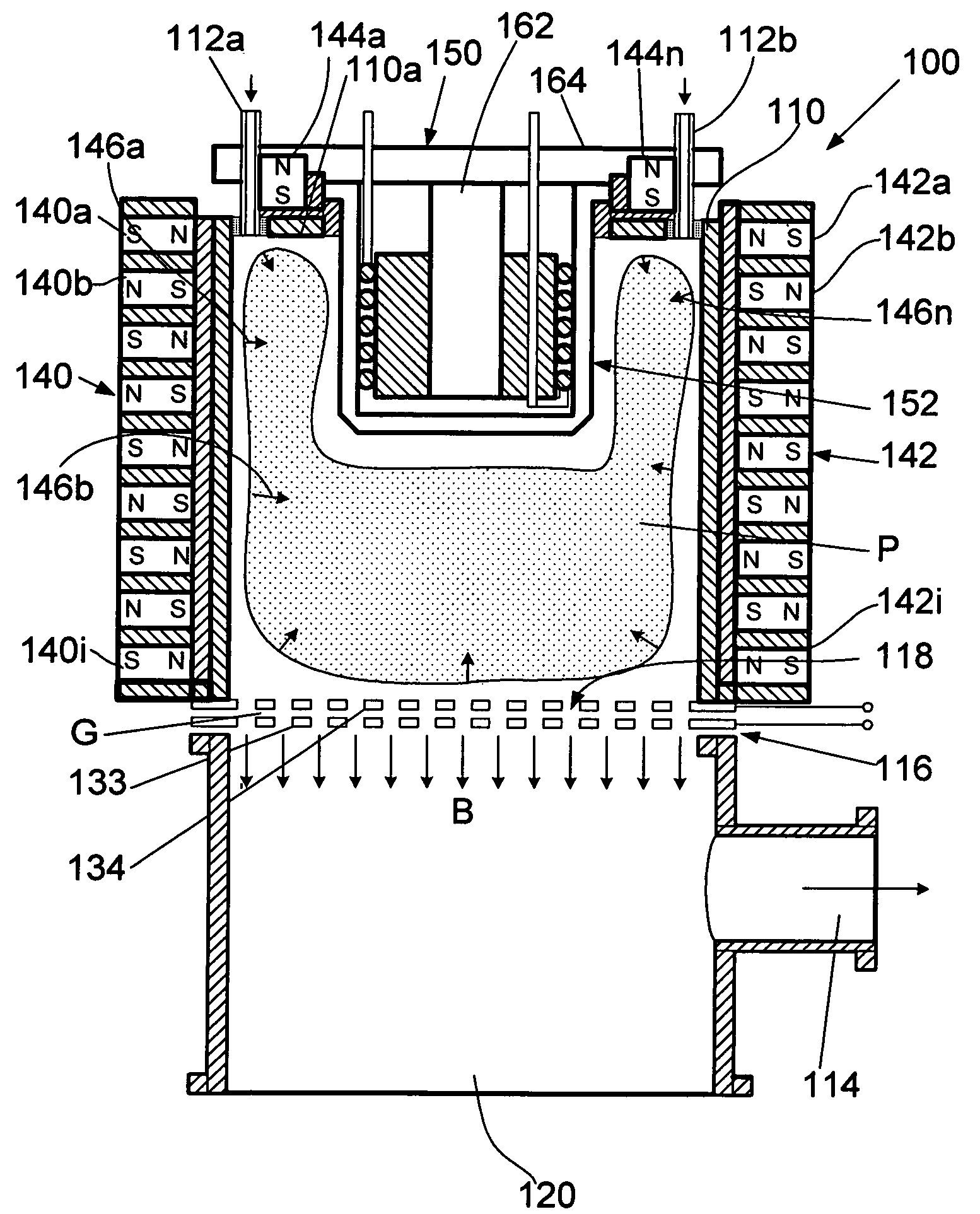
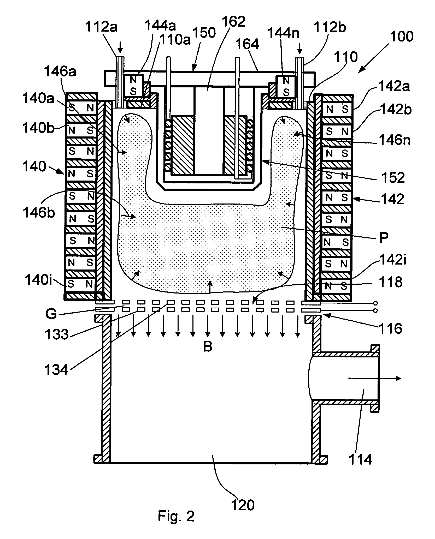
[0032]A general vertical sectional view of an ion-beam source of the invention is shown in FIG. 2. The ion-beam source, which in general is designated by reference numeral 100 consists of a sealed working chamber 110 that is formed from a non-magnetic metal or dielectric, e.g., ceramics, and ion-beam extractor system 116 that includes two grids 133 and 134 (FIG. 2) included into the electrical circuits shown in FIG. 3. The grids 133 and 134 are positioned at an exit opening 118 of the plasma chamber 110. The ion-beam extraction unit 116 is an important element for the formation of an ion beam B.

[0033]The working chamber 110 has a working-gas input pipe or pipes 112a and 112b for admission of a working gas, such as Ar, O2, N2, etc., into the working chamber 110 and a gas exhaust duct 114 formed in the side wall of the lower portion 120 of the ion-beam extractor system 116.

[0034]The lower portion 120 of the ion-beam extractor system 116 can be used for placing objects (not shown) that...


PUM


Abstract

An ion-beam source comprising: a plasma-generation unit for generating plasma and an ion-extraction unit for extraction and acceleration of ions from the aforementioned plasma, where the ion-extraction unit is made in the form of at least one grid under a negative potential. The plasma generating unit consists of a working chamber having a deeply immersed antenna cell. The cell contains a ferromagnetic core, a heat conductor with a heat sink, at least one inductive coil wound onto the ferromagnetic core, and a cap made from a dielectric material that sealingly covers the ferromagnetic core and the inductive coil.

Description

FIELD OF THE INVENTION[0001]The preset invention is related to a charged-particle source and particular to an ion-beam source based on the use of a new method of excitation of plasma by means of an immersed antenna cell or array of RF antenna cells having a ferromagnetic core or cores, respectively. The ion source of the invention may find application in systems that require obtaining high ion currents for treating surfaces of semiconductor wafers with an ion beam, implanting impurities, etching, application of coatings, space propulsion, etc.BACKGROUND OF THE INVENTION[0002]A typical source of charged particles, such as electrons or positive ions, which is intended for extraction of electrons or ions, includes a plasma chamber made of graphite, stainless steel, aluminum, etc., and an extraction electrode system for extracting charged particles confined in the plasma chamber. The plasma chamber of a typical ion source consists of a top wall, side walls, and a bottom wall. A pluralit...

Claims


Application Information

Patent Timeline
IPC IPC(8): H01J27/00
CPCH01J27/18
Inventor GODYAK, VALERY
Owner GODYAK VALERY
Why Eureka
Try Eureka