
Bottom-up electrospinning devices, and nanofibers prepared by using the same

Inactive Publication Date: 2009-07-30
FINETEX TECH GLOBAL +1
View PDF7 Cites 21 Cited by
  • Summary
  • Abstract
  • Description
  • Claims
  • Application Information

AI Technical Summary

Benefits of technology

[0097]The present invention enables an infinite nozzle arrangement by arranging a plurality of nozzles on a flat nozzle block plate upon electrospinning of nanofibers, and is capable of enhancing productivity per unit time with the improvement of

Problems solved by technology

The aforementioned conventional bottom-up electrospinning devices and the method for producing nanofibers using the same is problematic in that a spinning liquid is continuously fed to nozzles with a high voltage applied thereto to thereby greatly deteriorate the electric force effect.
Meanwhile, a conventional horizontal electrospinning devices with nozzles and a collector arranged in a horizontal direction has a drawback that it is very difficult to arrange a plurality of nozzles for spinning.
That is, it is difficult to arrange the nozzles located on the uppermost line, the nozzles located on the lowermost line and the collector at the same spinning distance (tip-to-collector distance) in order to raise a nozzle plate including nozzles and a spinning liquid in a direction horizontal to the collector, thus there is no alternative but to arrange a limited number of nozzles.
However, in the conventional electrospinning devices, it is impossible to arrange a limited number of nozzles in a predetermined space as explained above, thus making mass production needed for commercialization difficult.
The conventional electrospinning devices has a problem that electrospinning is mostly done at about one hole level and this disables mass production to make commercialization difficult.
Further, the conventional horizontal electrospinning devices has another problem that there occurs a phenomenon (hereinafter, referred to as ‘droplet’) that a polymer liquid aggregate not spun through the nozzles is adhered to a collector plate, thereby deteriorating the quality of the product.

Method used

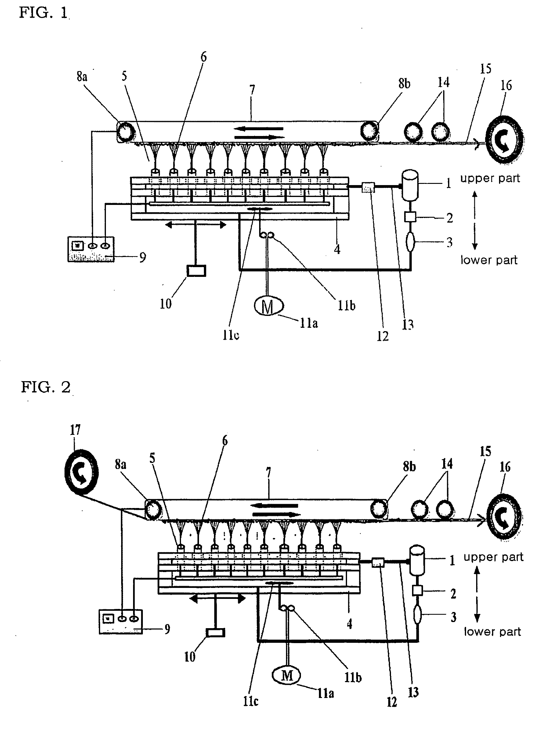
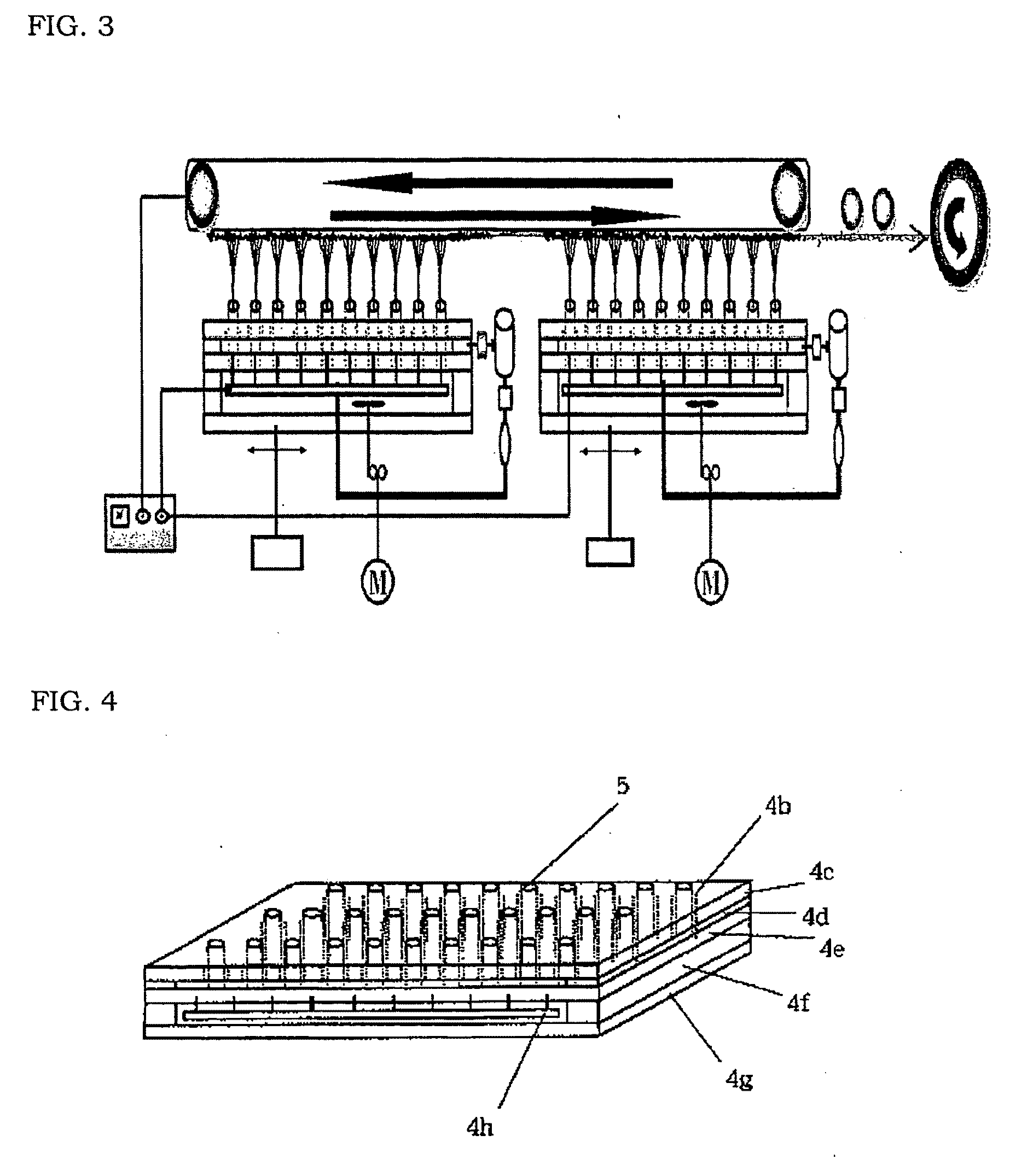

Image

  • Bottom-up electrospinning devices, and nanofibers prepared by using the same
  • Bottom-up electrospinning devices, and nanofibers prepared by using the same
  • Bottom-up electrospinning devices, and nanofibers prepared by using the same

Examples


example 1

[0101]Chips of nylon 6 having a relative viscosity of 3.2 (determined in a 96% sulfuric acid solution) were dissolved in formic acid to prepare a 25% spinning liquid. The spinning liquid had a viscosity of 1200 centipoises (cPs) measured by using Rheometer-DV, III, Brookfield Co., USA, an electric conductivity of 350 mS / m measured by a conductivity meter, CM-40G, TOA electronics Co., Japan, and a surface tension of 58 mN / m measured by a tension meter (K10St, Kruss Co., Germany).

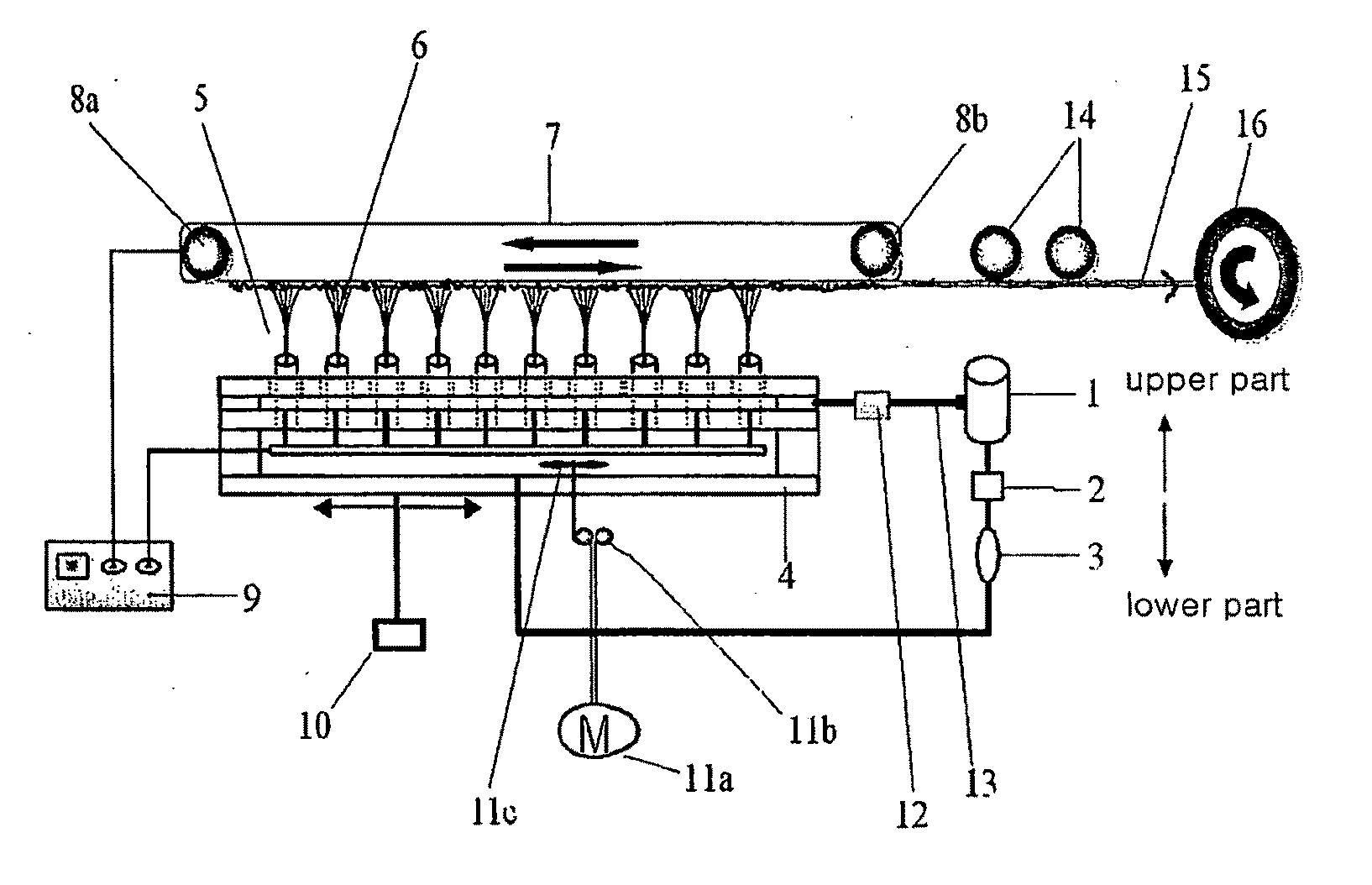
[0102]The spinning liquid was stored in a spinning liquid main tank 1, quantitatively metered by a metering pump 2, and then fed to a spinning liquid dropping device 3 to discontinuously change the flow of the spinning liquid. Continually, the spinning liquid was fed to a nozzle block 4 of a bottom-up electrospinning devices as shown in FIG. 1 with a 35 kV voltage applied thereto, spun bottom-up onto fibers through nozzles and collected on a collector 7 located on the top part to produce a nonwoven fabric web...

example 2

[0103]Chips of nylon 6 having a relative viscosity of 3.2 (determined in a 96% sulfuric acid solution) were dissolved in formic acid to prepare a 20% spinning liquid. The spinning liquid had a viscosity of 1050 centipoises (cPs) measured by using Rheometer-DV, III, Brookfield Co., USA, an electric conductivity of 350 mS / m measured by a conductivity meter, CM-40G, TOA electronics Co., Japan, and a surface tension of 51 mN / m measured by a tension meter (K10St, Kruss Co., Germany).

[0104]The spinning liquid was stored in a main tank 1, quantitatively metered by a metering pump 2, and then fed to a spinning liquid dropping device 3 to discontinuously change the flow of the spinning liquid. Continually, the spinning liquid was fed to a nozzle block 4 of a bottom-up electrospinning devices as shown in FIG. 1 with a 35 kV voltage applied thereto, spun bottom-up onto fibers through nozzles and electrospun on a collector 7 located on the top part. Meanwhile, a polypropylene nonwoven fabric ha...

example 3

[0105]A niobium oxide (NbO2 of 50 weight parts in a solution state) sol solution was prepared from niobium ethoxide by a general sol-gel process. That is, 1,000 g of niobium was dissolved in 1000 g of ethanol and 3 g of acetic acid was added thereto. Then, the mixture was stirred at 40° C. with approximately 100 rpm. After two hours, a sol solution in dim yellow was obtained. Acetic acid functions to prevent precipitation in the preparation of sol and acts as a catalyst for hydrolysis and condensation. 2,500 g of a solution made by dissolving in acetone 14 weight parts of polyvinyl acetate was mixed with 2,000 g of a niobium oxide sol solution. The mixed solution was stirred for 5 hours at 35° C. with 60 rpm. By using this solution, electrospinning was carried out by a bottom-up electrospinning devices. The spinning liquid was stored in a main tank 1, quantitatively metered by a metering pump 2, and then fed to a spinning liquid dropping device 3 to discontinuously change the flow o...


PUM

PropertyMeasurementUnit
Timeaaaaaaaaaa
Angleaaaaaaaaaa
Massaaaaaaaaaa

Abstract

A conventional electrospinning devices is problematic in that the productivity is low and a droplet, by which a spinning liquid is not formed into fiber but dropped in a drop shape, occurs, to thereby deteriorate the quality of a nonwoven fabric. To solve the above problem, the present invention provides an bottom-up electrospinning devices, comprising: a spinning liquid main tank 1; a metering pump 2; a nozzle block 4; nozzles 5 installed on the nozzle block; a collector 7 for collecting fibers being spun from the nozzle block; and a voltage generator 9 for applying a voltage to the nozzle block 4 and the collector 7, wherein [A] the outlets of nozzles 5 installed on a nozzle block are formed in an upper direction; [B] a collector 7 is located on the top part of the nozzle block; and [C] a spinning liquid discharge device 12 is connected to the uppermost part of the nozzle block 4.

Description

TECHNICAL FIELD[0001]The present invention relates to a bottom-up electrospinning devices which is capable of mass production of fibers having a nano level thickness (hereinafter, ‘nanofiber’), and a nanofiber produced using the same.[0002]Products such as nonwoven fabrics, membranes, braids, etc. composed of nanofibers are widely used for daily necessaries and in agricultural, apparel and industrial applications, etc. Concretely, they are utilized in a wide variety of fields, including artificial leathers, artificial suede, sanitary pads, clothes, diapers, packaging materials, miscellaneous goods materials, a variety of filter materials, medical materials such as gene transfer elements, military materials such as bullet-proof vests, and the like.BACKGROUND ART[0003]A conventional electrospinning devices and a method for producing nanofibers using the same disclosed in U.S. Pat. No. 4,044,404 are described as follows. The conventional electrospinning devices comprises: a spinning li...

Claims


Application Information

Patent Timeline
IPC IPC(8): B29C47/00B29C47/08D01D1/06D01D4/00D01D5/00D01D5/04D01F6/00D04H1/728
CPCD01D5/0084D01D5/0061
Inventor KIM
Owner FINETEX TECH GLOBAL
Learn More