Self starting permanent magnet synchronous motor

Inactive Publication Date: 2009-08-13
HITACHI LTD
View PDF4 Cites 40 Cited by
  • Summary
  • Abstract
  • Description
  • Claims
  • Application Information

AI Technical Summary

Benefits of technology

[0034]Since the fluorine compound layer shows higher resistance than NdFeB-based magnetic particles at a temperature of 800 degrees C. or below, the resistance of the NdFeB sintered magnet can be increased by forming the fluorine compound layer, and as a result, an eddy current loss can be reduced.
[0035]The fluorine compound layer may contain as an impurity an element, if it does not exhibit a ferromagnetic property at around room temperature at which an effect on the magnetic properties is small, other than the fluorine compound. Fine particles of a nitrogen compound or carbide may be mixed into the fluorine compo

Problems solved by technology

But, magnetic coercivity, residual magnetic flux density, squareness of a demagnetization curve, thermal demagnetizing properties, magnetizability, anisotropy, corrosion resistan

Method used


Image

  • Self starting permanent magnet synchronous motor
  • Self starting permanent magnet synchronous motor
  • Self starting permanent magnet synchronous motor

Examples


example 1

Explanation of Self-Starting Permanent Magnet Synchronous Motor

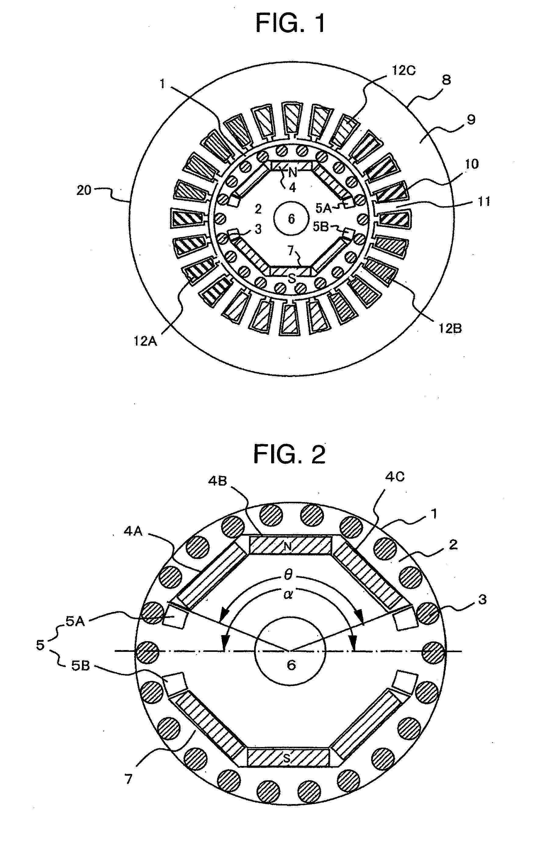
[0054]FIG. 1 shows a radial cross-sectional view showing an example of a permanent magnet type synchronous motor according to the present invention.

[0055]In FIG. 1, a self-starting permanent magnet synchronous motor 20 comprises a stator 8 and a rotor 1.

[0056]The stator 8 has a stator iron core 9, plural (24 in the drawing) slots 10 formed therein, and teeth 11 divided by the slots 10. Armature windings 12 comprising U-phase windings 12A, V-phase windings 12B and W-phase windings 12C are wound by distributed winding with the same phase distributed in the plural slots 10.

[0057]By configuring as described above, when the armature windings 12 are supplied with a fixed frequency AC voltage, the rotor 1 can be activated and accelerated as an induction motor, and then it becomes possible to perform a constant-velocity drive as a synchronous motor.

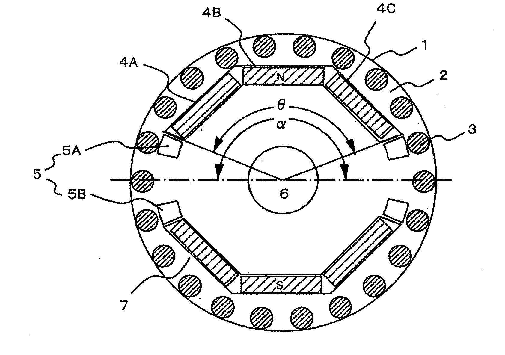
[0058]FIG. 2 is a radial cross-sectional view of a rotor of a synchronous motor a...

example 2

[0080]A DyF3 or TbF3 layer is formed on Nd2Fe14B magnetic particles having a high residual magnetic flux density to which a high magnetic coercivity provision element such as Dy, Tb, Pr or the like is not added. Thus, a high residual magnetic flux density and a high magnetic coercive force can be achieved. A cast ingot is produced by dissolving an alloy having a composition similar to Nd2Fe14B according to a high frequency dissolving method. The ingot is formed into 1 to 10 μm powder by a pulverizer. To form a fluorine compound layer on the powder surface, gelatinous DyF3.XH2O or TbF3.XH2O is subjected to centrifugal separation. A solvent removed processing liquid is mixed with the NdFeB powder, the solvent is evaporated from the mixture, and hydrated water is evaporated by heating.

[0081]The powder is subjected to horizontal magnetic field pressing or vertical magnetic field pressing to orient the magnetic particles in a magnetic field of 0.5 T to 1 T, sintered in inert gas or in va...

example 3

[0085]Quenched powder mainly composed of Nd2(Fe, Co)14B is produced as NdFeB-based powder, and a fluorine compound is formed on the surface of the obtained powder. The quenched powder may contain amorphous. To form DyF3 on the quenched powder surface, Dy(CH3COO)3 is dissolved as a raw material in H2O, and HF is added. The addition of HF produces gelatinous DyF3.XH2O. It is subjected to centrifugal separation to remove the solvent, and it is mixed with the NdFeB powder. The solvent is evaporated from the mixture, and hydrated water is evaporated by heating. The formed fluorine compound layer having a film thickness of 1 to 1000 nm was examined by XRD. As a result, it was found that the fluorine compound film was comprised of DyF3, DyF2, DyOF or the like.

[0086]The magnetic powder having a particle diameter of 1 to 300 μm is heated while preventing it from being oxidized at a temperature of less than 800 degrees C. which is a heat treatment temperature at which the magnetic properties ...


PUM

PropertyMeasurementUnit
Grain sizeaaaaaaaaaa
Fractionaaaaaaaaaa

Abstract

The present invention provides a permanent magnet that a fluorine compound is formed on the surfaces of Fe-based magnetic particles, and a recoil permeability is determined in a range of 1.05 to 1.30 by controlling an iron concentration in the fluorine compound to a range of 1 to 50% to reduce a loss due to magnetization rotation, thereby remedying reduction of a residual magnetic flux density and degradation of steady-state characteristics.

Description

BACKGROUND OF THE INVENTION[0001]The present invention relates to a rare earth magnet applied to a self-starting permanent magnet synchronous motor.[0002]In recent years, improvement of characteristics of various motors is an essential proposition in view of environmental protection. Therefore, there are many needs for replacing a conventional heavily used induction motor by a magnet motor having a permanent magnet field.[0003]A self-starting permanent magnet synchronous motor can make full-voltage start up by direct feeding of commercial power similar to an induction motor, and in steady operation, it is driven with high efficiency as a magnet motor. Therefore, it is not necessary to add an inverter and the above motor has features that it can be applied relatively easily by replacing the induction motor as energy saving measures for devices heretofore used at a constant-velocity drive.[0004]But, the self-starting permanent magnet synchronous motor has a larger start-up current as ...

Claims


Application Information

Patent Timeline
IPC IPC(8): H02K21/46B22F1/08B22F1/16
CPCB22F1/02C22C32/00C22C2202/02H02K21/46H01F1/112H02K1/02H02K1/223H01F1/09B22F1/16B22F1/08
Inventor KIKUCHI, SATOSHISATSUU, YUUICHIKOMURO, MATAHIROMIKAMI, HIROYUKITAKAHASHI, AKESHI
Owner HITACHI LTD
Why Eureka
Try Eureka