Process for Manufacturing a Microreactor and Its Use as a Reformer

Inactive Publication Date: 2009-10-08
ATOTECH DEUT GMBH
View PDF4 Cites 6 Cited by
  • Summary
  • Abstract
  • Description
  • Claims
  • Application Information

AI Technical Summary

Benefits of technology

[0067]The method variants mentioned above allow for a gentle treatment of the reactor layers since the bonding temperature can be selected to be as low as possible. With the bonding methods indicated, the bond seams obtained exhibit high homogeneity, corrosion stability and strength. Ideally, a monolithic structure is formed, that is to say that no bond seam is visible in a cross sectional photomicrograph, even after appropriate preparation of the sample. The thickness of the deposited bonding layers preferably ranges from 0.2 to 100 μm, preferably from 1 to 40 μm. By controlling the quantity of molten phase, it is made certain that the passageways are not obstructed by the (brazing) solder. In the event a bonding method is used in which the bonding temperature is set t

Problems solved by technology

These forms of commercializing coatings and catalysts cannot, or only conditionally, be used for micro-structured reactors.
This is due for example to the risk of clogging of the channels, the increased pressure drop, the inhomogeneous flow profile, the inhomogeneous concentration and temperature profiles resulting therefrom as well as the appearance of the hot/cold spots, which are all due to the form given to the catalyst.
The inlet and outlet regions are thus also contaminated with the catalyst or even completely coated so that reactions occur prematurely or continue to occur outside of the structured reactor core.
This may result in poorer temperature control and, as a result thereof, in poorer reaction control, in undesired side reactions and in reduced conversion and reduced selectivity.
To a large extent, the advantages of the micro-structure technology are thus lost.
Major disadvantages are the risk of leakage, which involves potential leakage of hazardous substances as well as poorer thermal coupling.
For this reason, seals are needed in reactors bonded this way, said seals significantly limiting the applicable temperature range.
However, all the methods of bonding micro-structured reactors presently preferably used in practice do not allow for a pre-coat method for applying the catalyst because of the process conditions and/or the additives used (e.g., fluxing agents):
Another disadvantage of this method is the long holding and processing time.
The high temperature required makes the use of diffusion welding for pre-coat temperature-sensitive catalysts totally inadequate.
The lack of bond across the webs generally leads to poorer thermal coupling of the various reactor layers.
Transverse leaks may further appear between the various passageways, such leaks leading to undesired mixtures and reactions.
This may happen at the expense

Method used


Image

  • Process for Manufacturing a Microreactor and Its Use as a Reformer
  • Process for Manufacturing a Microreactor and Its Use as a Reformer
  • Process for Manufacturing a Microreactor and Its Use as a Reformer

Examples


Example

EXAMPLE 1

Micro-Structured Reactor Made from AlMg3 for Methanol Steam Reforming

[0084]Metal sheets made from AlMg3 were structured by means of photolithography and chemical etching. For this purpose, one of the methods described in DE 197 08 472 C2 were used. For each reactor layer, 63 channels having a cross section of 0.5 mm×0.23 mm and a length of 47 mm were formed in the metal sheet. The overall volume of the channels of one metal sheet was 294 mm3. Further, a cover plate and a bottom plate were produced for terminating the reactor stack. Through bores for the reactor connections were drilled in the cover plate.

[0085]Prior to applying a bonding layer onto the bonding areas and the passageways, the reactor sheet was cleaned and pre-treated. This procedure comprised the following discrete steps: 1) degreasing, 2) pickling, 3) zincate pickling (such steps and the chemicals needed therefore are generally known in this art). After a homogenous zincate layer has been produced in the las...

Example

EXAMPLE 2

A Micro-Structured Reactor Made from Nicrofer 3220H and Bonded at 800° C. for Methane Steam Reforming:

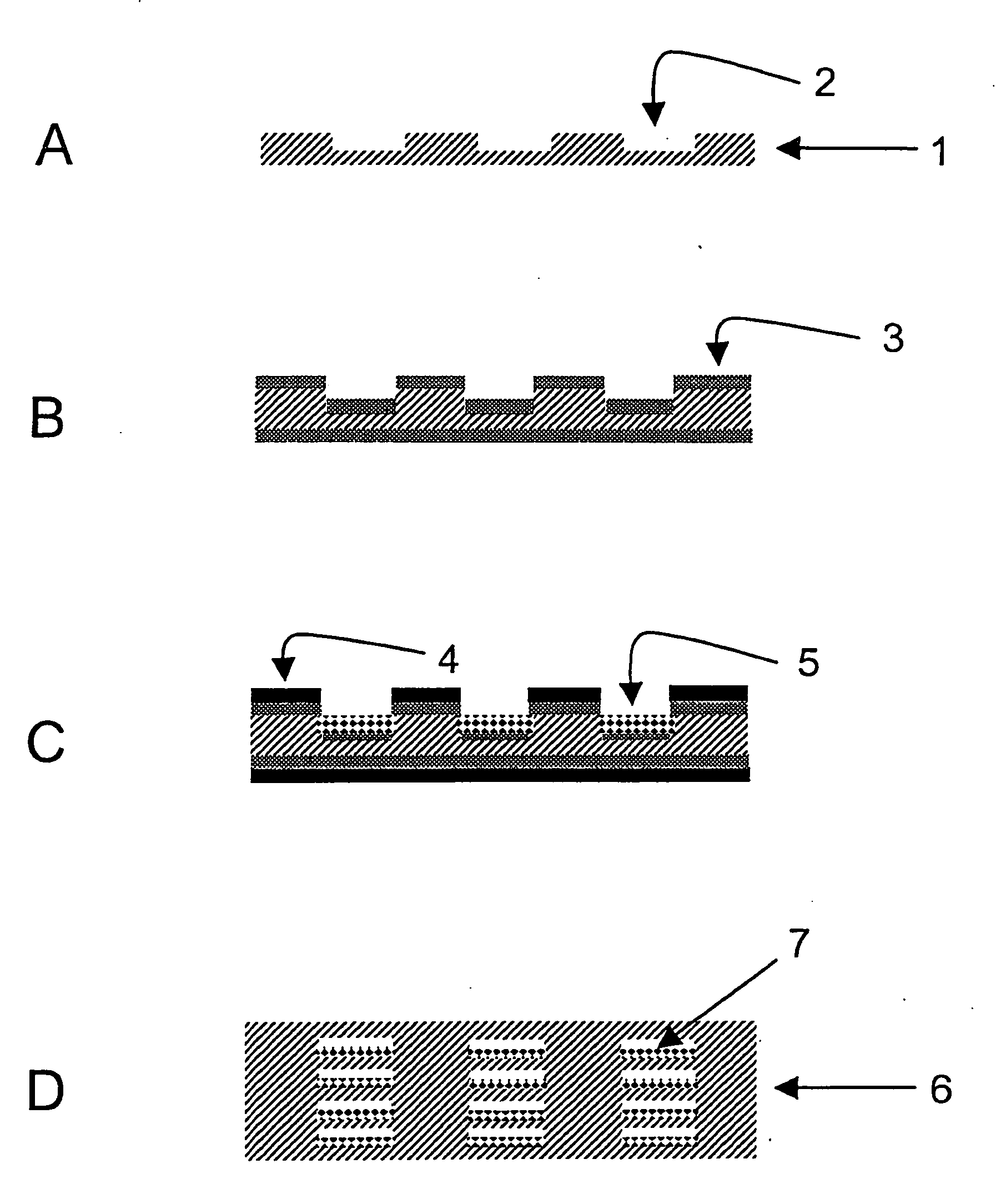
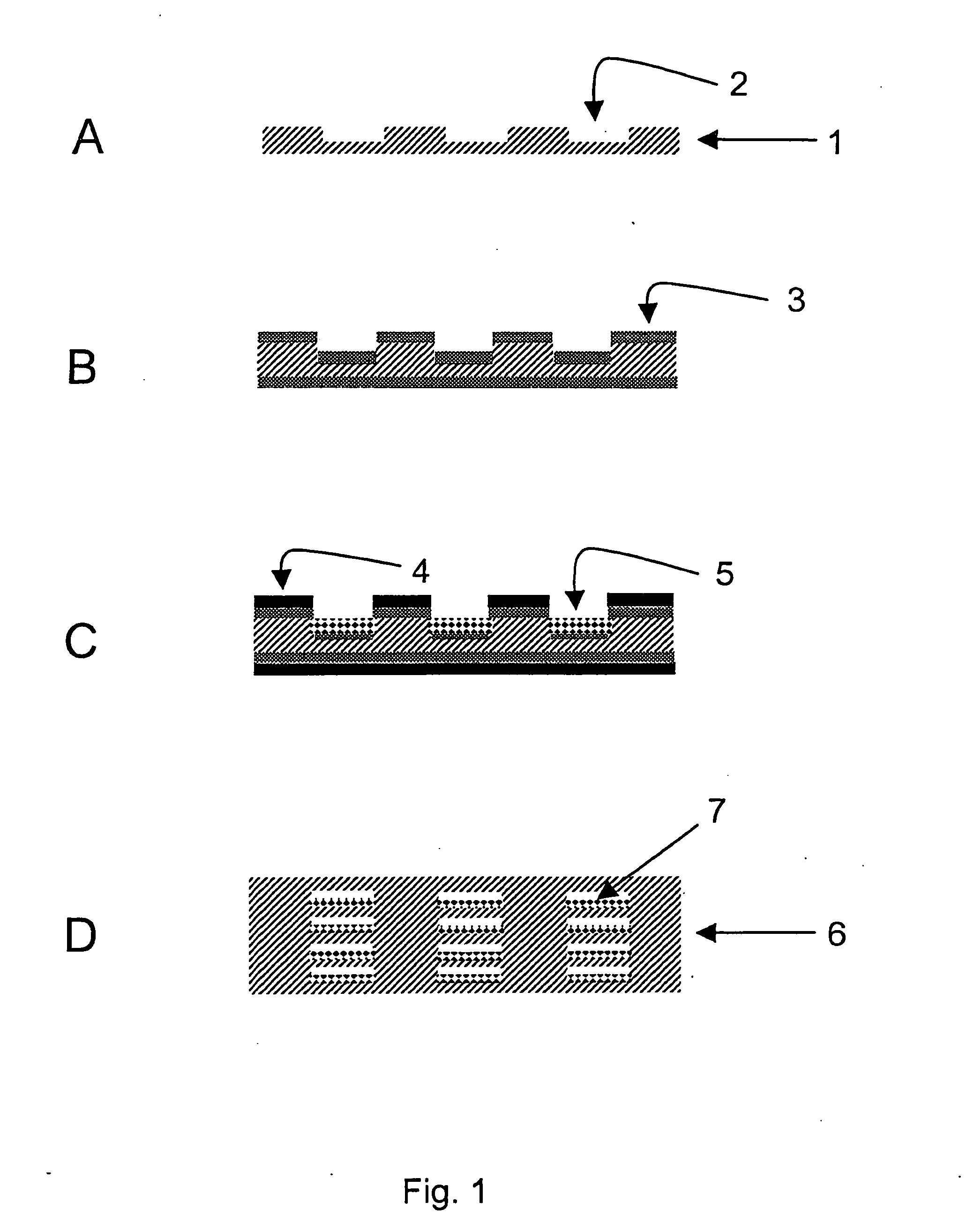
[0102]Metal sheets made from Nicrofer 3220H were structured by means of photolithography and chemical etching. For this purpose, one of the methods described in DE 197 08 472 C2 were used. For each reactor layer, 21 channels having a cross section of 0.5 mm×0.25 mm and a length of 28 mm were formed in the metal sheet. The overall volume of the channels of one metal sheet was 115 mm3. Further, a cover plate and a bottom plate were produced for terminating the reactor stack. Through bores for the reactor connections were drilled in the cover plate.

[0103]Prior to applying a bonding layer onto the bonding areas and the passageways, the reactor sheet was cleaned and pre-treated. This procedure comprised the following discrete steps: 1) degreasing, 2) pickling, 3) electrolytic degreasing, 4) etch cleaning / pickling. In the last pre-treatment step, metallic deposition of the bondin...

Example

EXAMPLE 3

A Micro-Structured Reactor Made from Nicrofer 3220H and Bonded at 1100° C. for Methane Steam Reforming

[0109]The process sequence for producing the reactor corresponds to the one described in Example 2 except that this reactor was bonded for 1 h at a temperature of 1100° C. This temperature corresponds to the temperature typically used for diffusion welding with this material Nicrofer 3220H.

[0110]The performance data of the micro-structured reactor for methane steam reforming are summarized in Table 1 and FIG. 5.

[0111]It could be evidenced that[0112]1. According to the method of the invention, the performance of the reactor bonded at 800° C. (Example 2) is significantly increased over the performance of the reactor bonded at 1100° C. (Example 3) with respect to educt conversion at the same working point; this allowed showing that the reduction of the bonding temperature according to the method of the invention directly has a positive influence onto the catalyst activity and,...


PUM


Abstract

For manufacturing micro-structured reactors with passageways loaded with catalyst using the pre-coat method, a method is provided which comprises the following method steps: a) producing reactor layers having bonding areas as well as passageway areas in which the passageways are formed, b) applying at least one bonding layer onto the reactor layers in the bonding areas, c) loading the reactor layers in the passageway areas with the catalyst and d) bonding the reactor layers, the bonding layer being applied and masked before the reactor layers are loaded with the catalyst. As a result, it is ensured that the efficiency of the catalyst will not be affected during manufacturing. The reactor may be used as a methane and methanol reformer in particular.

Description

FIELD OF THE INVENTION[0001]The present invention relates to a method of manufacturing a chemical reactor which comprises passageways loaded with catalyst as well as to the use of a reactor manufactured in accordance with the invention as a hydrocarbon and alcohol reformer.BACKGROUND ART[0002]As a result of increasing miniaturization and of the need of ever more efficient energy management, both in terms of processing and engineering, in the design of components and systems (system integration) of chemical reactors, micro-structured reactors, heat exchangers and coolers (micro-structured components) are used both in research and development projects and even start to be utilized in first industrial processes. Micro-structured components generally consist of a stack of thin metal sheets which are characterized by fine structures. Components having very fine channels are obtained by bonding the structured metal sheets. The metal sheets may be structured by dry etching, wet chemical de...

Claims


Application Information

Patent Timeline
IPC IPC(8): F01N7/18C23F1/04B01J35/02C10G35/04F01N13/18
CPCB01J19/0093B01J2219/00783B01J2219/00804Y10T29/49345B01J2219/00835B01J2219/0086B01J2219/00822B01J19/00C01B3/38C01B3/32
Inventor KURTZ, OLAFHERBER, RALPHMADRY, CHRISTIANSCHAFER, GERD
Owner ATOTECH DEUT GMBH
Why Eureka
Try Eureka