Thin film transistor

a thin film transistor and transistor technology, applied in the direction of electrical equipment, semiconductor devices, electric discharge tubes, etc., can solve the problems of not always improving element characteristics of a tft, the nuclei generation position and nuclei generation density cannot be controlled directly, and the formation of no advantage over a polycrystalline silicon film, etc., to achieve the reduction of defect levels, the effect of increasing the current and reducing the off current of the thin film transistor

Inactive Publication Date: 2009-10-29
SEMICON ENERGY LAB CO LTD
View PDF99 Cites 21 Cited by
  • Summary
  • Abstract
  • Description
  • Claims
  • Application Information

AI Technical Summary

Benefits of technology

[0025]In the semiconductor layer in which the plurality of crystal regions and the plurality of minute crystal grains are included in the amorphous structure, generation density and generation positions of the crystal regions can be controlled. Further, the semiconductor layer includes the NH group, thereby reducing defect levels at an interface between the crystal region and the amorphous structure, at an interface between the minute crystal grain and the amorphous structure, and at a crystal grain boundary. With use of such a semiconductor layer as a channel formation region of the thin film transistor, the on current can be increased. Further, with provision the buffer layer over the semiconductor layer, the off current of the thin film transistor can be reduced.

Problems solved by technology

However, in a method of forming a microcrystalline silicon film in such a manner that after an amorphous silicon film is formed, a photothermal conversion layer formed using a metal material is provided and laser irradiation is performed, crystallinity can be improved; however, in terms of productivity, there is no advantage over a polycrystalline silicon film formed by laser annealing.
Finding in a model of growth of microcrystalline silicon that peculiar silicon-hydrogen bonding is observed on an amorphous surface when nuclei of microcrystalline silicon start to grow is effective; however, nuclei generation positions and nuclei generation density cannot be controlled directly.
Further, even if the purity of a microcrystalline silicon film is improved and the impurity concentration is reduced, whereby a microcrystalline silicon film, the crystal grain size of which becomes large and defect density of which (especially, the defective charge density) is reduced, can be obtained, it means only change in physical property values of a microcrystalline silicon film and it does not always improve element characteristics of a TFT or the like.

Method used


Image

  • Thin film transistor
  • Thin film transistor
  • Thin film transistor

Examples


embodiment 1

[0065]In this embodiment, an example of a mode of a thin film transistor will be described with reference to the drawings.

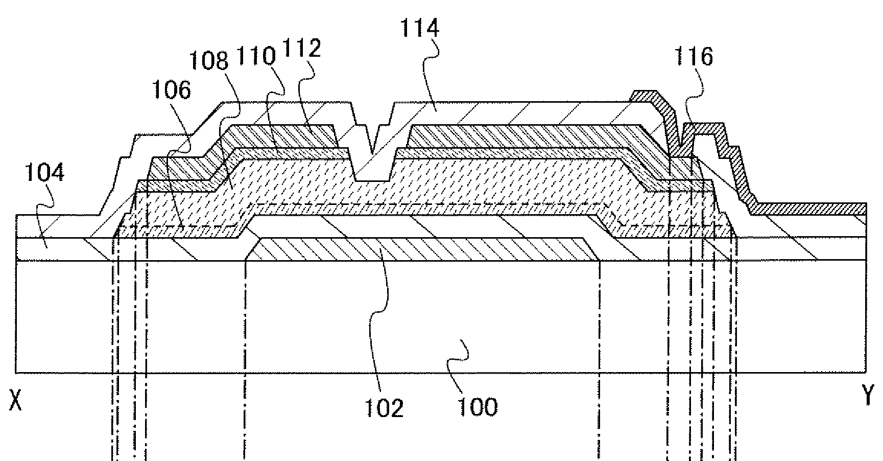
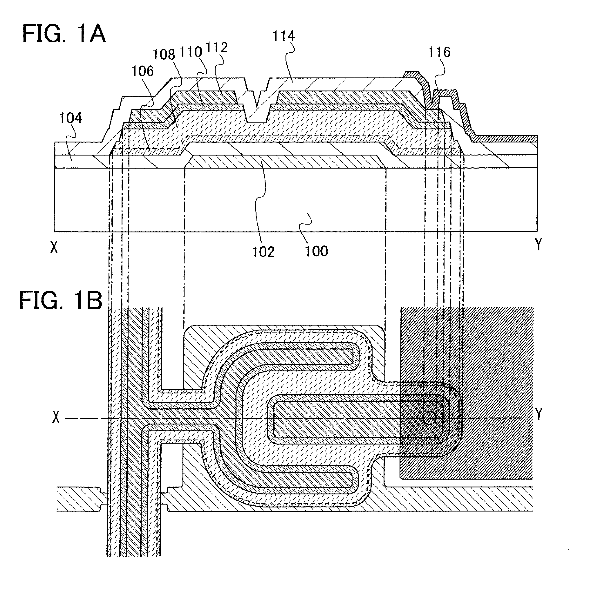
[0066]FIGS. 1A and 1B are a top view and a cross sectional view each illustrating a thin film transistor according to this embodiment. The thin film transistor illustrated in FIG. 1A includes: a gate electrode layer 102 over a substrate 100; a gate insulating layer 104 covering the gate electrode layer 102; a semiconductor layer 106 which is formed over and in contact with the gate insulating layer 104; a buffer layer 108 over the semiconductor layer 106; and a source and drain regions 110 formed over and in contact with part of the buffer layer 108. Further, the thin film transistor includes wiring layers 112 provided over and in contact with the source and drain regions 110. The wiring layers 112 form a source electrode and a drain electrode. The thin film transistor includes, over the wiring layers 112, an insulating layer 114 functioning as a protective film....

embodiment 2

[0170]In this embodiment, a method for the thin film transistor illustrated in FIG. 1, which is different from those of Embodiments 1, will be described. In this embodiment, a semiconductor layer including minute crystal grains and crystal grains each having an inversed-conic or inversed-pyramidal is formed in a manner similar to that of Embodiments 1. However, a method by which nitrogen is included in the semiconductor layer is different from that described in Embodiments 1.

[0171]In this embodiment, a gate insulating layer which is in contact with a semiconductor layer is formed using a silicon nitride layer, whereby a nitride concentration of the semiconductor layer is controlled and the semiconductor layer including minute crystal grains and crystal grains each having an inverted conical or inverted pyramidal shape is formed. A series of steps from a step of forming a gate insulating layer 104 to a step of forming an impurity semiconductor layer 109 imparting one conductivity typ...

embodiment 3

[0181]In this embodiment, a method for manufacturing the thin film transistor illustrated in FIG. 1, which is different from those of Embodiment 1 and Embodiment 2, will be described. In this embodiment, a semiconductor layer including minute crystal grains and inverted conical or inverted pyramidal grains is formed in a manner similar to those of Embodiment 1 and Embodiment 2. However, a method by which nitrogen is included in the semiconductor layer is different from those in Embodiment 1 and Embodiment 2.

[0182]In this embodiment, the inside of a treatment chamber is cleaned before deposition of a semiconductor layer. Then, an inner wall of the chamber is covered with a silicon nitride layer, whereby the semiconductor layer includes nitrogen and the oxygen concentration is suppressed low, so that the nitrogen concentration is made higher than the oxygen concentration. A series of steps from a step of forming a gate insulating layer 104 to a step of forming an impurity semiconducto...


PUM


Abstract

The thin film transistor includes a gate insulating layer covering a gate electrode, over a substrate having an insulating surface; a semiconductor layer forming a channel formation region, in which a plurality of crystal regions is included in an amorphous structure; an impurity semiconductor layer imparting one conductivity type which forms a source region and a drain region; and a buffer layer formed from an amorphous semiconductor, which is located between the semiconductor layer and the impurity semiconductor layer. The thin film transistor includes the crystal region which includes minute crystal grains and inverted conical or inverted pyramidal grain each of which grows approximately radially from a position away from an interface between the gate insulating layer and the semiconductor layer toward a direction in which the semiconductor layer is deposited in a region which does not reach the impurity semiconductor layer.

Description

BACKGROUND OF THE INVENTION[0001]1. Field of the Invention[0002]The present invention relates to a thin film transistor and a method for manufacturing the same, and a semiconductor device and a display device using the thin film transistor.[0003]2. Description of the Related Art[0004]Thin film transistors (hereinafter also referred to as “TFTs”) are already widely used in a technical field of liquid crystal displays. A TFT is a kind of field-effect transistor, and is named after the fact that a semiconductor film for forming a channel is formed thin. At present, a technique to manufacture a TFT using amorphous silicon or polycrystalline silicon for the thin semiconductor film has already been put into practical use.[0005]A semiconductor material called “microcrystalline silicon” has been known for a long time together with amorphous silicon and polycrystalline silicon, and there also has been a report on microcrystalline silicon related to a field-effect transistor (for example, see...

Claims


Application Information

Patent Timeline
Patent Type & Authority Applications(United States)
IPC IPC(8): H01L29/786
CPCH01J37/32091H01L27/1214H01L29/04H01L27/1288H01L29/78669H01L29/78678H01L29/78696H01L29/66765H01L27/1218H01L27/127
Inventor DAIRIKI, KOJIMIYAIRI, HIDEKAZUISA, TOSHIYUKIMIYANAGA, AKIHARUHIROHASHI, TAKUYAYAMAZAKI, SHUNPEIWATABE, TAKEYOSHI
Owner SEMICON ENERGY LAB CO LTD
Why Eureka
Try Eureka