Adjustable molecular motor micropower biosensor and its application

Inactive Publication Date: 2009-11-05
INSITUTE OF BIOPHYSICS CHINESE ACADEMY OF SCIENCES
View PDF5 Cites 0 Cited by
  • Summary
  • Abstract
  • Description
  • Claims
  • Application Information

AI Technical Summary

Benefits of technology

[0007]After exhaustive study, the inventors of the present invention found that by using fluorescence probe as a sensitive signal sensor of the rotation of the molecular motor, the rotation signal of the molecular motor can be easily obtained without being linked to a heavy load. Antibody technology was further used to regulate the rotation function of the molecular motor. The invention also relates to the use of the fluorescence as a biological micropower sensor.
[0010]Furthermore, a rotary biosensor assembles a molecule recognition and signal conversion device, as well as a bioactive element into a whole simple setup (see FIG. 11A). Fluorescence technology was used to detect the rotation speed of the motor. Linking of different loads (object to be tested) to the motor results in different rotation speeds. A variety of methods such as using chemical, light, outside force, etc. can be applied to regulate the rotation speed. The rotation time can be in seconds, minutes, hours, or even days (as desired). Because of the difference in the detection mechanism, the rotary sensor of the present invention not only has high sensitivity, but also high resolution. In addition, the rotary sensor of the present invention does not need special labeling, which saves time and is of importance in quick application process.Mechanism of Molecule Detection
[0012]The change of the fluorescence intensity is directly related to the rotation speed of the molecular motor, and the rotation speed is further related directly to the size / quantity of the molecule loaded. Therefore, the less the motor being loaded with the molecules, the faster the rotation speed of the motor. In such a case, the magnitude that fluorescence changes from week into strong becomes more dramatic and faster. On the other hand, the more / heavier the motor being loaded with the molecules, the slower the rotation speed of the motor. In such a case, the magnitude that the fluorescence changes from week into strong becomes less dramatic and slower. Accordingly, the rotation speed (fast / slow) of the motor and thus the loading situation of the motor can be determined from the magnitude changes of the fluorescence signal. Since the relationship between the magnitude changes of the fluorescence signal and the rotation process of the molecular motor is accumulative, even there is only relatively minor difference among the molecules loaded, a high detection accuracy can still be achieved.Initiation and Regulation of the Rotation of the Molecular Motor
[0015]As the size of the load relates directly to the rotation speed of the c subunit of F0 coupled to γε, and the rotation speed of the c subunit of F0 is coupled with the transport speed of protons, we can easily determine the loading situation of F1 part with a fluorescence pH probe, which is used to test the transport speed of protons (as shown in FIG. 11A). Our pilot study has indicated the method is fast, sensitive, and easy to use.
[0016]The ultrasensitive molecule biosensor of the present invention has a molecular motor and has immunological recognition function, the mechanism of which is clear and reliable (see FIG. 11A).
[0034]The molecular motor micropower biosensor of the present invention is highly sensitive and regulable. After subjected to appropriate modification (e.g., combining with antibodies of a specific biological macromolecule or a viral molecule antigen), the biosensor can detect target biological macromolecule or viral molecule in single molecule level. Hopefully, the molecular motor micropower biosensor of the present invention will be developed into a new generation of micropower single molecule sensor. It will step up the manufacture technologies of biosensor and nanomaterial into a higher lever, and promote revolutionary development in a variety of industries such as biochips, biopharmaceuticals, national defense, environment, energy, and information. The biosensor of the present invention can be applied to many fields and will generate massive economic and social benefits.

Problems solved by technology

Currently, since nanomotor technology is far from mature, it is still not possible for researchers to produce nanoengine.
However, because the protein filament (about 1-2 μM in length) is a too heavy load for the molecular motor which is only 10 nm in length, the sensitivity of the detection is low and difficult to regulate.
Therefore, though promising, two major issues seriously impede the application and development of molecular motor: 1. lack of regulatory techniques for molecular motor; and 2. difficulties in expressing the signal of molecular motor rotation in high sensitivity.

Method used


Image

  • Adjustable molecular motor micropower biosensor and its application
  • Adjustable molecular motor micropower biosensor and its application
  • Adjustable molecular motor micropower biosensor and its application

Examples


example 1

The Assembly of Adjustable Molecular Motor Micro Power Biosensor

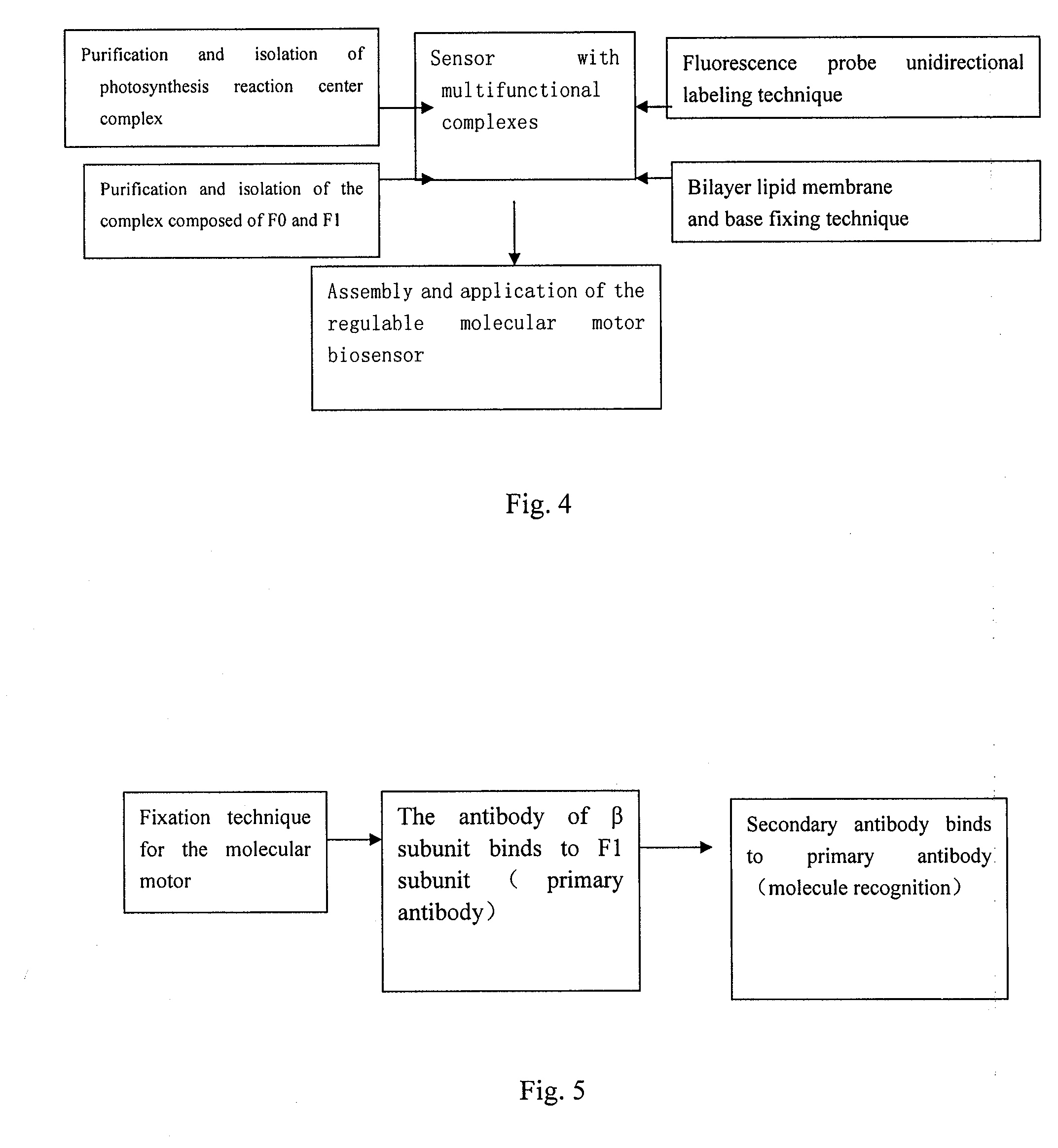
[0054]As shown in FIG. 4, the molecular motor micropower biosensor was assembled.

(1) Preparation of the Photosynthesis Complex (Chromatophores) of the Molecular Element.

[0055]Culturing photosynthesis bacteria (R. capsulatus, 120, available from the cell bank of Institute of Microorganism, Chinese Academy of Science, (Accession number 1.2359)). Culture medium: KH2PO4, 1.0 g, MgCl2 0.5 g, CaCl2 0.1 g, NaCl 1.0 g, sodium acetate 1.0 g, sodium succinate 1 g, yeast extract, 1.0 g, NaHCO3 0.5 g, peptone 0.5 g (OXOID Great Britain), trace elements 1.0 ml, vitamin solution 1.0 ml, distilled water 1.0 L, pH 6.8, 8 pounds, autoclaved for 30 minutes. Components in the vitamin solution: biotin 0.1 g (Imported), nicotinic acid 0.35 g, Thiamine dichloride 0.3 g, Ca-panthothenate 0.1 g, Vitamin B12, 0.05 g, Pyridoxolium Hydrochloride, Fluka 0.1 g, distilled water 1.0 L; components of the trace elements: FeCl2 4H2O 1.8 g; CoCl2 6H2O 0....

example 2

Fluorescence Signal of the Molecular Motor Micropower Biosensor without Load

(1) Detecting Method of the Sensor

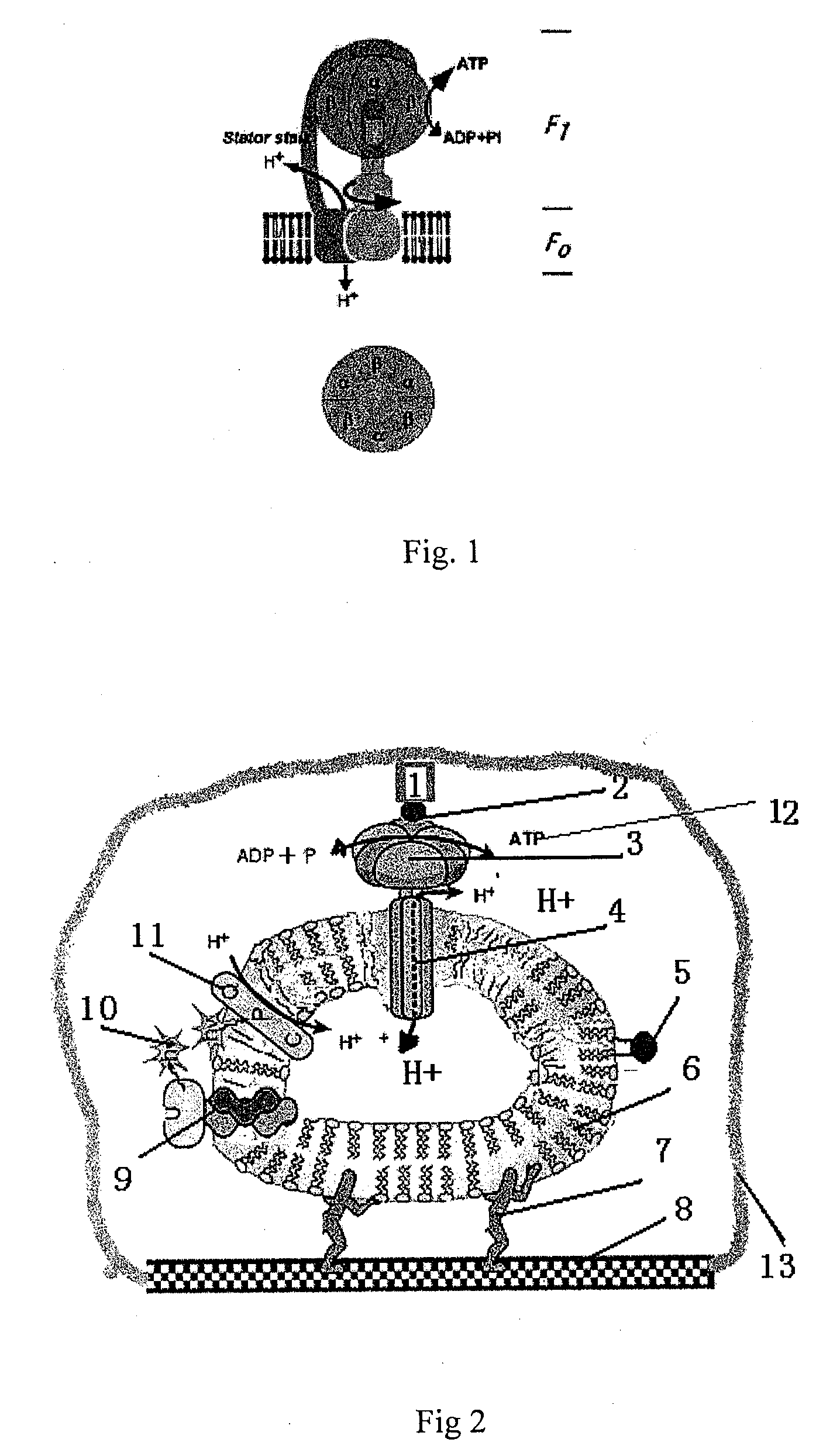
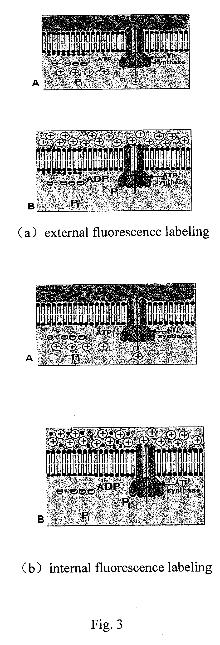
[0060]The sample was placed onto a glass surface or into a fluorescence well (1 ml) (Hitachi apparatus, type F-4500). The sample was exited at 488 nm, with emission wavelength of 520 nm. When the sample was initiated with 2 mM ATP (Sigma company), the molecular motor of the present invention will transport the protons from the external to the internal of the cell. As a result, F1 rotated in counter-clockwise, increasing the extracellular pH from 8.0 to 9.0. At this time, the signal can be recorded conveniently by fluorescence probe Lipids-fluorescein located outside (or inside) of the cell membrane. If the molecular motor was loaded with different weight of loads (e.g., loaded with one antibody), its rotation speed will change significantly, which can be conveniently recorded by fluorescence probe Lipids-fluorescein (or fluorescein) located outside (or inside) of the cell me...

example 3

Fluorescence Signal of Molecular Motor Micropower Biosensor with Different Load

[0065]Preparation of the Antibody of the β Subunit: the Expression of Thermophilic Bacteria Bacillas PS3 and the purification of p subunit were carried out according to literatures (Science Reports, 2004, (13)1342-1347). The purified p subunit was emulsified with adjuvant in 1:1 before inoculation. The β subunit was inoculated at multiple spots on the dorsal of a 250 g rabbit (initially injected with 1 ml once every two weeks). One month later, the immunization was boosted 1-2 times to obtain polyclonal antibodies.

[0066]Based on the molecular motor micropower biosensor setup in Example 1, the p subunit primary antibody specifically bond to the p subunit of F1-ATP motor. Another IgG (goat-anti-rabbit, Sigma, Imported) secondary antibody can specifically recognize the primary antibody of the p subunit, thus completing the setup of a pair of molecular motors, the load difference between which is only of thre...


PUM


Abstract

A regulable molecular motor micropower biosensor comprises: a rotary motor, an optical energy conversion device, a signal molecular output device, a power resource system, a protective layer, a supporting material, and a bilayer lipid membrane fixing material. The molecular motor micropower biosensor is used for detecting biological macromolecules, viral molecules, etc.

Description

FIELD OF THE INVENTION[0001]The present invention relates to the field of nanometer biosensor of the power engine of a nanoscale device. More particularly, the present invention relates to an adjustable molecular motor micropower biosensor. The present invention further relates to the use of the regulable molecular motor in the detection of biological macromolecules, viral molecules, etc.DESCRIPTION OF THE PRIOR ART[0002]Nowadays, technologies in fields such as electron device, chemical industry and life sciences have come into the era of nanoscience. Molecular motor is believed to be the growing point of new technologies such as nanomechanical materials due to its extraordinary functions. Because biomotors (power engines of nanoscale devices) and nanoscale devices can not work without energy supply, there is a need for micromotors in molecular-scale.[0003]Some technological innovations are marked by newly discovered energy to mechanical work conversion. The invention of steam engin...

Claims


Application Information

Patent Timeline
IPC IPC(8): G01N33/53C12Q1/34
CPCG01N33/543C12Q1/34
Inventor YUE, JIACHANG
Owner INSITUTE OF BIOPHYSICS CHINESE ACADEMY OF SCIENCES
Why Eureka
Try Eureka