
Process for Using Hydrated Iron Oxide and Alumina Catalyst for Slurry Hydrocracking

a technology of iron oxide and catalyst, which is applied in the field of crude oil processing and equipment for hydrocracking slurry, can solve the problem of limiting the rate at which iron sulfide can form, and achieve the effect of good performance in sh

Inactive Publication Date: 2009-12-31
UOP LLC
View PDF31 Cites 7 Cited by
  • Summary
  • Abstract
  • Description
  • Claims
  • Application Information

AI Technical Summary

Benefits of technology

[0008]We have unexpectedly found that water does not affect the performance of the iron oxide and alumina catalyst. As much as about 23 wt-% and more water on the

Problems solved by technology
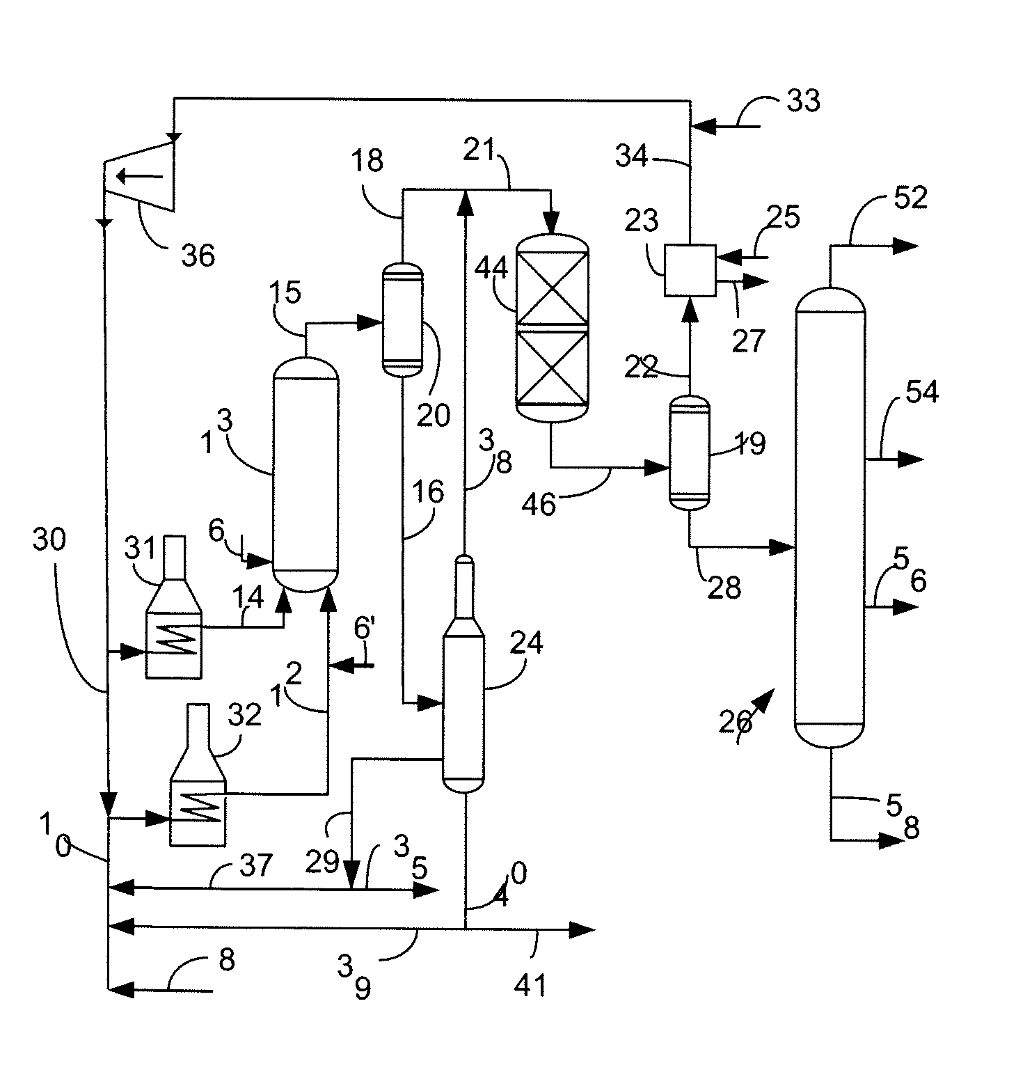
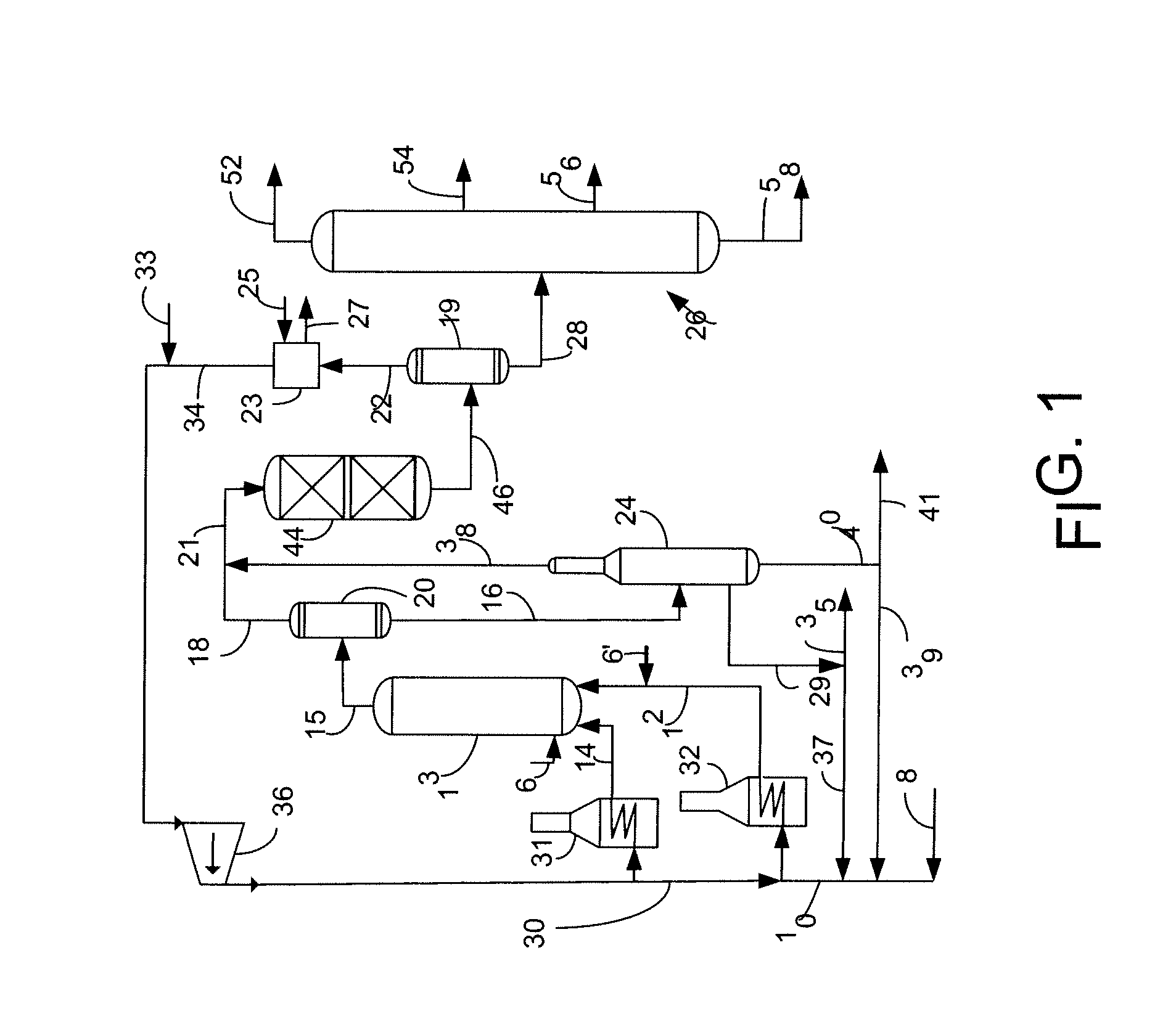
Consequently, the amount of water in the system may limit the rate at which iron sulfide can form.

Method used


Image

  • Process for Using Hydrated Iron Oxide and Alumina Catalyst for Slurry Hydrocracking
  • Process for Using Hydrated Iron Oxide and Alumina Catalyst for Slurry Hydrocracking
  • Process for Using Hydrated Iron Oxide and Alumina Catalyst for Slurry Hydrocracking

Examples


example 1

[0046]A feed suitable for SHC is characterized in Table I. Unless otherwise indicated, this feed was used in all the Examples.

TABLE IVacuum BottomsTest(975° F.+)Specific Gravity, g / cc1.03750API gravity−0.7ICP MetalsNi, wt. ppm143V, wt. ppm383Fe, wt. ppm68.8Microcarbon residue, wt-%25.5C, wt-%80.3H, wt-%9.0N, wt-%0.4Total N, wt. ppm5744Oxygen, wt-% in organics0.78Sulfur, wt-%7Ash, wt-%0.105Heptane insolubles, wt-%16.1Pentane insolubles, wt-%24.9Total chloride, mass ppm124Saybolt viscosity, Cst 150° C.1400Saybolt viscosity, Cst 177° C.410“ICP” stands for Inductively Coupled Plasma Atomic Emissions Spectroscopy, which is a method for determining metals content.

example 2

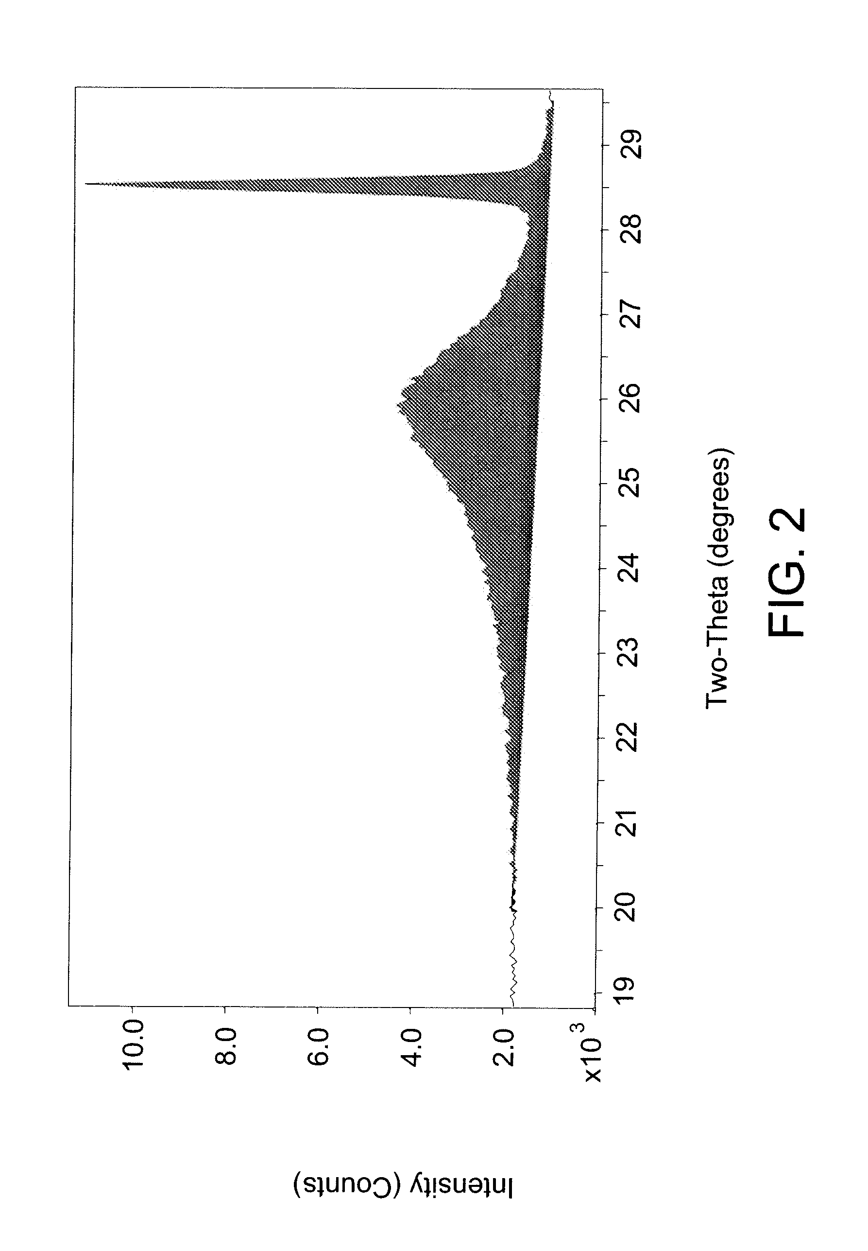
[0047]A TIOR sample from an SHC reaction using heavy oil feed from Example 1 and 0.7 wt-% iron content on iron sulfate monohydrate catalyst as a percentage of non-gaseous materials in the SHC reactor was analyzed for mesophase using an XRD method. A sample of SHC product material was blended with toluene, centrifuged and the liquid phase decanted. These steps were repeated on the remaining solids. The solids remaining were then dried in a vacuum oven at 90° C. for 2 hours. Silicon standard was added to the sample to give a concentration of 5.3 wt-% by adding silicon solid and acetone solvent to a sample of TIOR and slurried together with a mortar and pestle. The acetone evaporated out of the slurry to leave a solid comprising TIOR blended with silicon standard. An approximately 1 gram sample of the solid sample with blended standard was spread onto a XRD sample holder and placed into the XRD instrument and scanned using parameters of 2.0 / 70.0 / 0.04 / 10 (sec). The XRD instrument was a ...

example 3

[0049]In this example, we examined the ability of iron in iron sulfate monohydrate to convert to the active iron sulfide. Iron sulfate monohydrate was mixed with vacuum resid of Example 1 at 450° C. and 2000 psi (137.9 bar) in an amount such that 2 wt-% iron was present relative to the non-gaseous materials in the reactor. The temperature was chosen because it is the optimal temperature for pitch conversion for sulfur monohydrate catalyst. The semi-continuous reaction was set up so that hydrocarbon liquid and catalyst remained in the reactor; whereas, 6.5 standard liters / minute (sl / m) of hydrogen were fed through the reaction slurry and vented from the reactor. X-ray diffraction (XRD) characterization of solid material separated from vacuum resid feed during different stages of the reaction shows that the transformation of Fe(SO4).H2O to FeS is comparatively slow. FIG. 4 shows XRD patterns from samples taken from the semi-continuous reaction at various time intervals. FIG. 4 shows i...


PUM


Abstract

A process and apparatus is disclosed for converting heavy hydrocarbon feed into lighter hydrocarbon products. The heavy hydrocarbon feed is slurried with a catalyst comprising iron oxide and alumina to form a heavy hydrocarbon slurry and hydrocracked to produce lighter hydrocarbons. Performance of the iron oxide and alumina catalyst is not substantially affected by significant quantities of water on the catalyst.

Description

BACKGROUND OF THE INVENTION[0001]This invention relates to a process and apparatus for the treatment of crude oils and, more particularly, to the hydroconversion of heavy hydrocarbons in the presence of additives and catalysts to provide useable products and further prepare feedstock for further refining.[0002]As the reserves of conventional crude oils decline, heavy oils must be upgraded to meet world demands. In heavy oil upgrading, heavier materials are converted to lighter fractions and most of the sulfur, nitrogen and metals must be removed. Heavy oils include materials such as petroleum crude oil, atmospheric tower bottoms products, vacuum tower bottoms products, heavy cycle oils, shale oils, coal derived liquids, crude oil residuum, topped crude oils and the heavy bituminous oils extracted from oil sands. Of particular interest are the oils extracted from oil sands and which contain wide boiling range materials from naphthas through kerosene, gas oil, pitch, etc., and which c...

Claims


Application Information

Patent Timeline
IPC IPC(8): C10G47/04
CPCC10G47/26C10G47/04
Inventor BHATTACHARYYA, ALAKANANDRABRICKER, MAUREEN L.MEZZA, BECKAY J.BAUER, LORENZ J.
Owner UOP LLC
Learn More