Implant and Method for Manufacturing Same

a manufacturing method and implant technology, applied in the field of implants and manufacturing methods, can solve the problems of implant loss, vascular occlusion, and gradual overgrowth of the stent, and achieve the effects of reducing the risk of vascular occlusion, and reducing the effect of vascular occlusion

Active Publication Date: 2010-04-08
BIOTRONIK AG
View PDF20 Cites 34 Cited by
  • Summary
  • Abstract
  • Description
  • Claims
  • Application Information

AI Technical Summary

Benefits of technology

[0015]Consequently, the object of the present invention is to provide a method for manufacturing an implant, which will allow degradation of the implant in the desired target corridor. The degradation should take place at a c...

Problems solved by technology

Although an optimum vascular cross section, which is needed primarily for successful treatment, can be achieved by using stents or other implants, the permanent presence of such a foreign body initiates a cascade of microbiological processes, leading to a gradual overgrowth of the stent and in the worst case to a vascular occlusion.
As a result of this process, the implant loses its mechanical integrity at a certain point in time.
Biodegradable magnesium implants, in particular magnesium stents, have proven to be especially promising for the aforementioned target corridor of degradation, but they lose their mechanical integrity and/or supporting effect too soon on the one hand, while on the other hand, the loss of integrity fluctuates greatly in vitro and in vivo.
This means that in the case of magnesium stents, the collapse pressure declines too rapidly over time and/or the reduction in the collapse pressure has an excessively greatly variability and therefore cannot be determined.
However, with the approaches mentioned so far, it is usually impossible to make the dissolution that occurs as a result of the degradation process and its resulting breakage of the stents occur in the required time window.
The result is that degradation of the implant begins either too earl...

Method used


Image

  • Implant and Method for Manufacturing Same
  • Implant and Method for Manufacturing Same

Examples


example 1

[0073]First a stent with a body consisting of a magnesium alloy, preferably WE43 (93 wt % magnesium, 4 wt % yttrium (W) and 3 wt % rare earth metals (E) not including yttrium) is made available.

[0074]Then the aqueous solution (electrolyte) is prepared by first pouring 500 mL distilled H2O into a glass beaker. Then the components of the aqueous solution are added in the order given below. It should be noted that the next following component may be added only after the preceding components have completely dissolved. The electrolyte is to be stirred constantly during this addition, which can be implemented with a magnetic stirrer (500 min−1), for example. The components should also be added slowly to prevent excessive evolution of heat. The electrolyte synthesis may preferably take place in a double-walled coolable container. The following components may be added (all the following percentage amounts are percent by weight (wt %)):

1. 100 mL / L ethylenediamine solution (99%),

[0075]100 g / L...

example 2

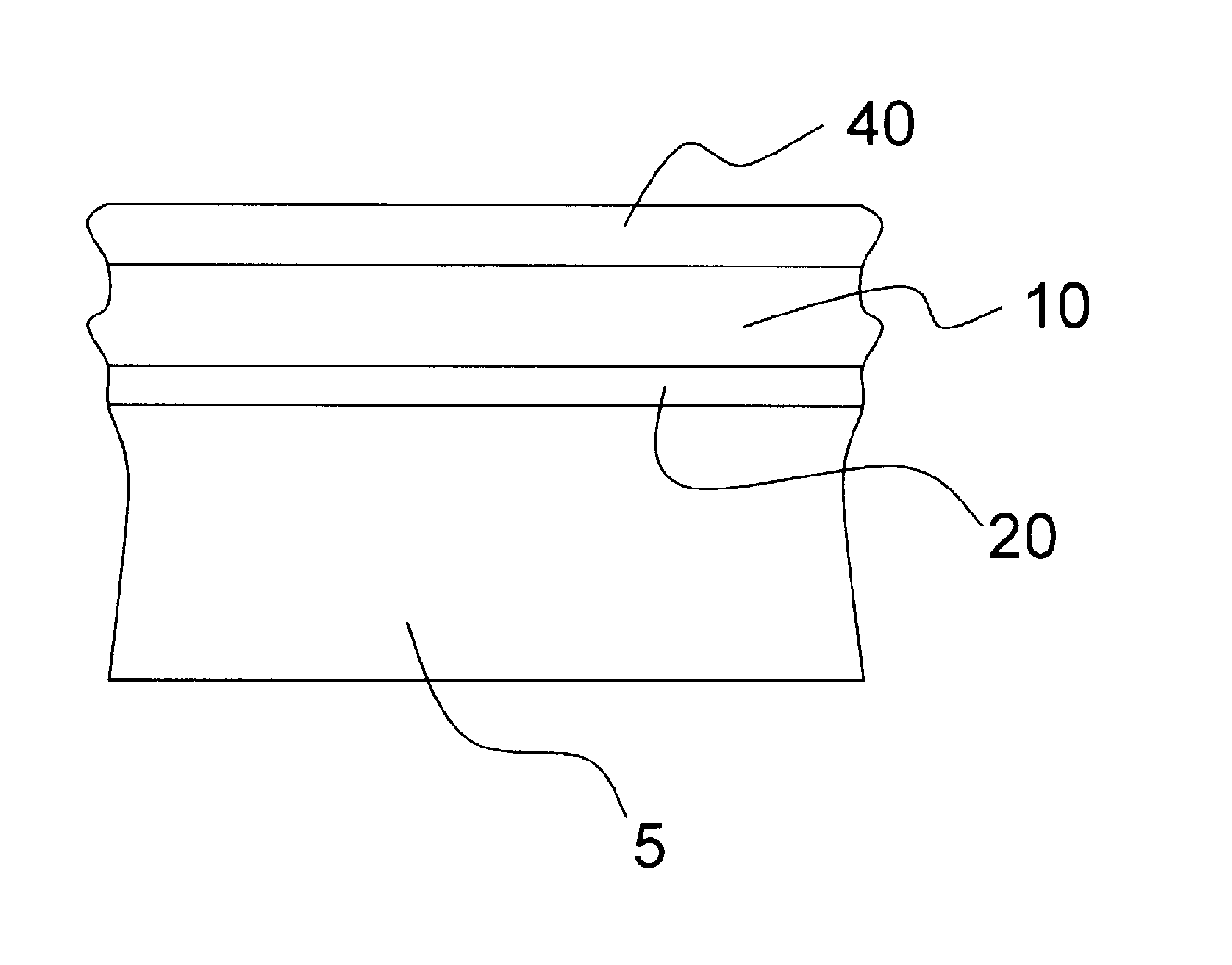
[0088]This example describes the coating of nonresorbable implants of nitinol, stainless steel or cobalt-chromium alloys or degradable materials with a second layer 20 of metals, containing at least one element from the group of tantalum, niobium, zinc, iron and aluminum. The implant is first produced with known technologies such as laser cutting, electropolishing, etc., forming a body 5 (see FIG. 1). Then the surface of the body 5 is coated with tantalum, niobium, zinc, iron, aluminum or an alloy containing these metals. The coating technologies used may include ionic liquids, sputtering, high-rate atomization or vaporization.

[0089]The second layer 20 is preferably produced with tantalum on a nitinol implant by means of an ionic liquid 1-butyl-1-methylpyrrolidiniumbis(trifluoromethylsulfonyl)amide from TaF5, forming a tantalum layer 20 that is 0.5 μm to 1 μm thick, adhering securely due to anodic preoxidation of nitinol in the ionic fluid, so that it is difficult to remove mechanic...

example 3

[0099]Like Example 2, which is incorporated herein.

[0100]After drying in a drying cabinet, instead of dipping the implant in or spraying it with polymer solutions as the first layer, the implant is dipped in aqueous or nonaqueous media in which bone morphogenetic proteins (BMPs) are dissolved, the latter being drawn into the pore structure by applying a vacuum, then remaining there after the drying process. so they have a positive influence on bone growth in the case of orthopedic implants.


PUM

PropertyMeasurementUnit
Temperatureaaaaaaaaaa
Timeaaaaaaaaaa
Timeaaaaaaaaaa

Abstract

The present invention proposes a method for manufacturing an implant, in particular an intraluminal endoprosthesis, having a body such that the body has metallic material. To control the degradation in a desired time window, e.g., between four weeks and six months, the following production method is performed: a) preparing the body of the implant, and b) plasma-chemical treatment of at least a portion of the surface of the body in an aqueous solution by applying a plasma-generating electric alternating voltage to the body (5) of the implant, said voltage having a frequency of at least approximately 1 kHz, to create a first layer. The invention also relates to an implant obtainable by such a method.

Description

CROSS REFERENCE TO RELATED APPLICATIONS[0001]The present invention claims benefit of priority to Germany patent application number DE 10 2008 042 602.4, filed on Oct. 6, 2008, the contents of which are herein incorporated by reference in their entirety.FIELD OF THE INVENTION[0002]The invention relates to a method for manufacturing an implant, in particular an intraluminal endoprosthesis.BACKGROUND OF THE INVENTION[0003]Medical endoprostheses or implants for a wide variety of applications are known in large numbers from the prior art. Implants in the sense of the present invention are understood to be endovascular prostheses or other endoprostheses, e.g., stents, fastening elements for bones, e.g., screws, plates or nails, surgical suture materials, intestinal clamps, vascular clips, prostheses in the area of hard and soft tissue as well as anchoring elements for electrodes, in particular pacemakers or defibrillators.[0004]Stents are a type of implant used especially frequently today...

Claims


Application Information

Patent Timeline
IPC IPC(8): A61F2/06B05D3/06
CPCA61L31/086A61L31/022
Inventor BAYER, ULLRICHSCHETTLER, JANEWERT, GUENTER
Owner BIOTRONIK AG
Why Eureka
Try Eureka