Display element and driving method thereof

a technology of display elements and components, applied in non-linear optics, instruments, optics, etc., can solve problems such as difficulty in mentioning sufficient performance, increase in electric power consumption, and difficulty in displaying white, and achieve the effect of simple structure of the element member

Inactive Publication Date: 2010-04-15
KONICA MINOLTA INC
View PDF4 Cites 22 Cited by
  • Summary
  • Abstract
  • Description
  • Claims
  • Application Information

AI Technical Summary

Benefits of technology

[0023]According to the present invention, a novel electrochemical display element exhibiting a bright white color, a high white-black contrast and a full color display with a simple structure of the element member, and a driving method thereof could be obtained.

Problems solved by technology

Particularly, when electronic information is in the form of text, it is necessary for an operator to watch the browsing means for a relatively long period of time, which is not a human-conscious operation.
Generally, it is known that emissive displays exhibit the following disadvantages: screen flickering results in eye fatigue; display devices are not portable; reading posture is limited; operators tend to gaze at a still screen; and reading over an extended period of time results in an increase of electric power consumption.
However, due to the following reasons, it is difficult to mention that sufficient performance has been achieved.
Namely, displays employing polarized plates such as reflective liquid crystals exhibit reflectance as low as approximately 40 percent, resulting in having a problem in displaying white.
Further, the production methods employed to prepare constituting members are not simple.
Polymer dispersion type liquid crystal displays require relatively high voltage, in addition, since only the difference in the refractive index among organic materials is utilized, the resulting images do not exhibit sufficient contrast.
Polymer network type liquid crystal displays result in problems in which a high voltage is required and in order to enhance memory functions, complicated TFE circuits are required.
Display elements based on an electrophoretic method necessitate voltage as high as at least 10 V, and durability problems may occur due to coagulation of electrophoretic particles.
In the former method, it is difficult to obtain a bright white display, in principal, due to the coloration of the color filter, and the latter method has a problem in that a dark black color cannot be obtained due to the use of a patter color.
When a display exhibiting a bright white color, a high white-black contrast and a color display is prepared using an electrochromic method, it is necessary to laminate three layers each exhibiting a different color, resulting in a high cost due to the complicated element constitution.
In this method, no fully sufficient white-black contrast has been obtained, since a dark black color cannot been obtained due to the flat color mixing structure.
Also, a method to use a poly pyridine compound in an electrochromic display has been known (for example, refer to Patent document 2), however, in this method, only two colors can be displayed and, specifically, a black display cannot be obtained.
An ED method is an excellent method to obtain a sufficient white-black contrast, however, color filters of B, G and R, or Y, M and C are needed in order to display a full color, whereby the excellent white-black contrast has not been fully utilized.

Method used


Image

  • Display element and driving method thereof
  • Display element and driving method thereof
  • Display element and driving method thereof

Examples


example 1

Preparation of Display Element 1

(Preparation of Electrolyte Liquid 1)

[0173]Added to 2.5 g of dimethyl sulfoxide were 0.15 g of sodium iodide, 0.1 g of silver iodide, 0.05 g of polyethylene glycol (average molecular weight: 500,000) and 0.01 g of Exemplified compound (1-68), which were completely dissolved, to obtain Electrolyte liquid 1.

(Preparation of Electrode 1)

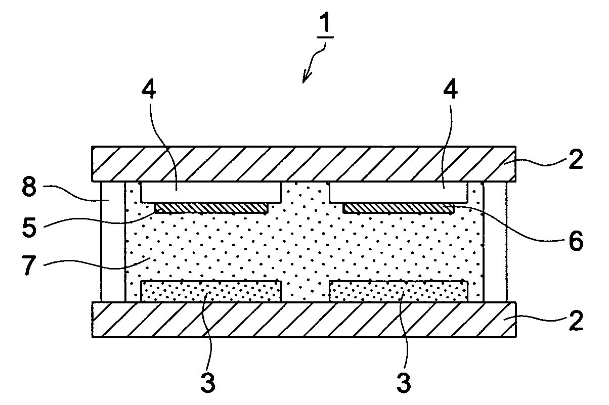
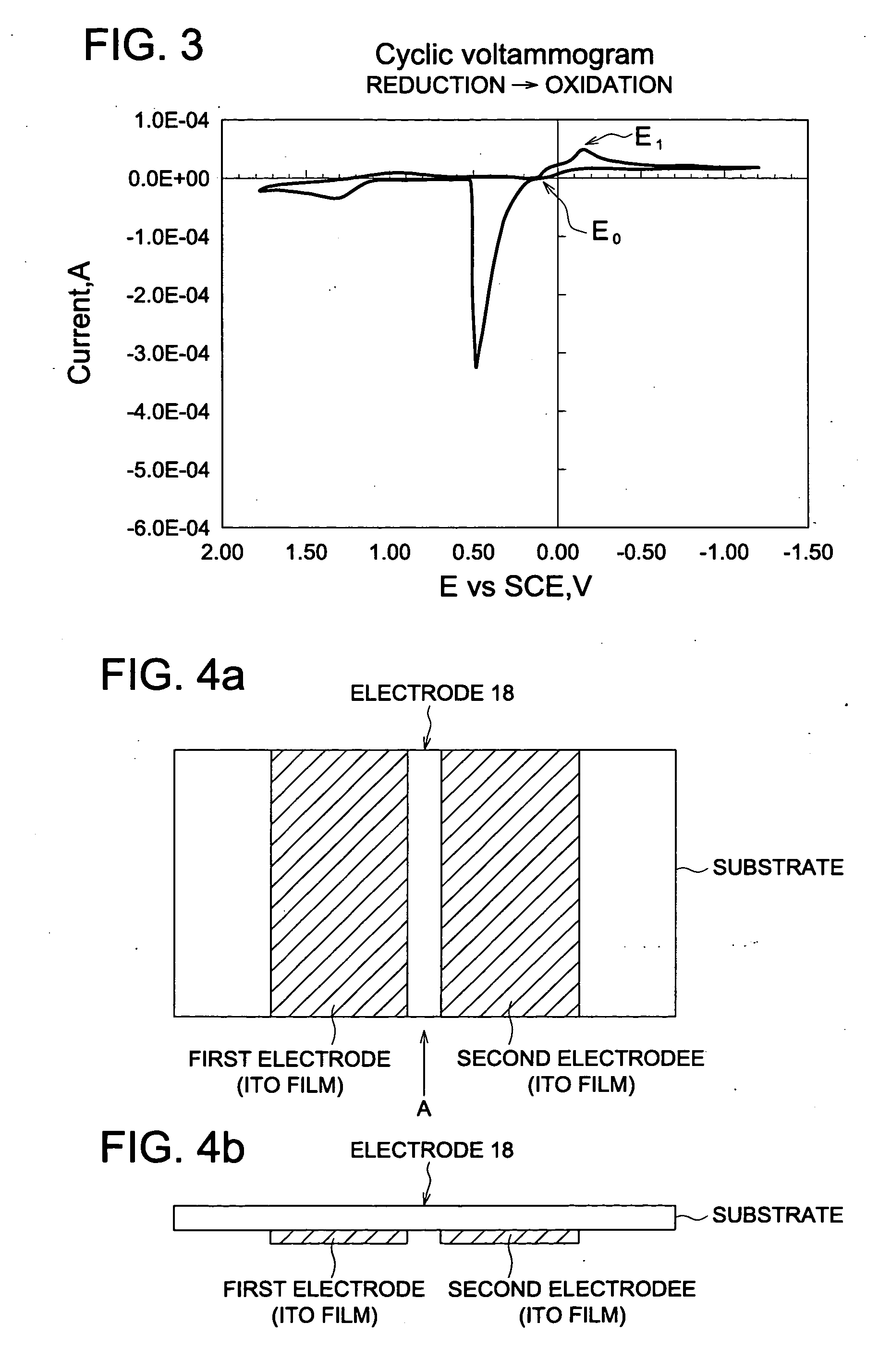
[0174]Films of ITO (Indium Tin Oxide) of 130 μm width with 145 μm interval were formed on a 1.5 mm thick 2 cm×4 cm glass substrate according to the method known in the prior art, whereby Electrode 1 which was a transparent electrode was obtained.

(Preparation of Electrode 2)

[0175]Silver-palladium electrodes of 0.8 μm thick and 130 μm width with 145 μm interval were formed on a 1.5 mm thick 2 cm×4 cm glass substrate according to the method known in the prior art, whereby Electrode 2 was obtained.

(Preparation of Electrode 3)

[0176]On Electrode 2 of which peripheral part was edged with an olefin sealant containing 10% by volume...

example 2

Preparation of Display Element 2

[0179]Electrolyte liquid 2 was prepared in the same manner as the preparation of Electrolyte liquid 1 use in Display element 1 described in Example 1 except that 0.3 g of titanium oxide was added in the electrolyte. Electrolyte liquids 3 and 4 were prepared in the same manner as the preparation of Electrolyte liquid 2 except that Exemplified compound (1-68: yellow) was changed to equimolar Exemplified compounds (1-70: magenta) and Exemplified compound (1-147: cyan), respectively.

[0180]The peripheral part of Electrode 2 described in Example 1 was edged with an olefin sealant containing 10% by volume of spherical glass beads having an average particles diameter of 20 μm, and further a dividing wall having windows of 100 μm square was formed using photolithography at pixels where Electrode 2 crossed with Electrode 1, whereby Electrode 4 was formed. Into the windows, Electrolyte liquids 2, 3, 4 were poured using a dispenser so as to form a Bayer arrangeme...

example 3

[0182]Inks 1-3 were prepared by dissolving 0.3 g each of Exemplified compound (1-73: yellow), Exemplified compound (1-74: magenta) and Exemplified compound (1-152: cyan), respectively, in 2.5 g of ethanol.

[0183]Added to 2.5 g of dimethyl sulfoxide were 0.1 g of silver iodide, 0.15 g of sodium iodide and polyethylene glycol (average molecular weight: 500), whereby Electrolyte liquid 5 was prepared.

[0184]Films of ITO of 130 μm width with 145 μm interval were formed on a 1.5 mm thick 2 cm×4 cm glass substrate according to the method known in the prior art and 10 g / m2 of titanium oxide (average particle diameter of 25 nm) was applied on it, followed by drying at 350° C. for 1 hour, whereby Electrode 5 applied with a porous metal oxide layer was obtained. Electrode 6 was prepared by separately applying Inks 1-3 on Electrode 5 so as to form a Bayer arrangement using a commercially available inkjet coating apparatus. Electrodes 6 and 1 were faced each other so that the striped electrodes o...


PUM

PropertyMeasurementUnit
distanceaaaaaaaaaa
distanceaaaaaaaaaa
diameteraaaaaaaaaa

Abstract

This invention provides a novel electrochemical display element, which can realize bright white display, high-contrast black and white display, and full-color display by a simple member construction, and a method for driving the display element. The display element is characterized in that it comprises opposed electrodes, and an electrolyte, an electrochromic compound, a metal salt compound, and a white scattering material between the opposed electrodes, and multicolor display of three or more colors is carried out by black display, white display, and display of color other than black by driving the opposed electrodes by taking advantage of 1) a color change as a result of oxidation and reduction reactions of the electrochromic compound, and 2) a color change as a result of reduction precipitation and oxidation dissolution of a metallic element contained in the metal salt compound in at least one of the opposed electrodes.

Description

TECHNICAL FIELD[0001]The present invention relates to a novel electrochemical display element which enables multicolor display with a one-layer structure of the display element, and a driving method thereof.BACKGROUND OF THE INVENTION[0002]In recent years, along with the increase in the operating speed of personal computers, the spread of network infrastructure, the markedly increased capacity of data storage, and the decrease in price, a further opportunity is increasing in which information such as text and images which have traditionally been supplied in the form of paper printed matter is now acquired and read as convenient electronic information.[0003]Employed as such electronic information reading means are conventional liquid crystal displays as well as CRTs, and in recent years, emissive displays such as organic EL displays are drawn attention. Particularly, when electronic information is in the form of text, it is necessary for an operator to watch the browsing means for a ...

Claims


Application Information

Patent Timeline
Patent Type & Authority Applications(United States)
IPC IPC(8): G02F1/153G02F1/155G02F1/1506G02F1/1503
CPCG02F1/1506G02F1/155G02F1/1521G02F1/1503
Inventor KOKEGUCHI, NORIYUKIHAKII, TAKESHIISHIGE, OSAMU
Owner KONICA MINOLTA INC
Why Eureka
Try Eureka