This helps you quickly interpret patents by identifying the three key elements:
Problems solved by technology
Method used
Benefits of technology
Benefits of technology
[0130]It is essential that the thermal treatment comprises heating the assembly at a temperature of at least 230° C., i.e. at a temperature exceeding melting point of polymer (F). Melting polymer (F) while maintaining the different layers coherently assembled advantageously enables sheet comprising polymer (F) to interpenetrate the surface asperities and protrusions of the photovoltaic elements assuring a good adhesion to said element with no need of additional tie layer, so that a proper front layer is formed in intimate contact with the light incident surface of the photovoltaic element. Via this
Problems solved by technology
However, there are problems for nuclear power generation in that it unavoidably produces radioactive wastes which are harmful for living things and there is a probability that leakage of injurious radioactive materials from the nuclear power generation system will happen when the system is damaged.
However, in the case of the aforementioned solar cell having the a-Si semiconductoractive layer disposed on the metal substrate, because the metal substrate does not permit incident light to transmit therethrough, light is impinged through the side opposite the metal substrate, and therefore, it is necessary to arrange an appropriate transparent protective member on the side through which light is impinged such that it protects the solar cell element.
This deterioration is caused by the reduction in the transmittance of the surface protective member which occurs when the protective member is yellowed or clouded as a result of deteriorated of the same.
No material is known, however, which simultaneously gives adequate insulation, weatherability, flexibility and impact strength, stain resistance, and adhesion to photovoltaic element, in the aforementioned surface coating or filler constitution, especially in the case where the solar cell is exposed to a natural environment for a long time, e.g. twenty years or more.
Fluororesins of the prior art, when used as the outermost surface layer, lose weatherability, often owing to loss of stabilizers contained therein by decomposition by U.V. light, water or heat, by volatilization or elution by heat or water for a long term of outdoor exposure of twenty years or more, resulting in deterioration of the solar cell.
In particular, tandem junction laminated photoactive semiconductorlayers, for which a non-monocrystalline semiconductor, preferably an amorphous silicon semiconductor is used, are greatly adversely affected in conversion efficiency by discoloration of surface coating material.
Therefore, if shorter wavelengths of light are absorbed by discoloured surface coating material, the photoactive semiconductor layer absorbing the shorter wavelengths of light generates less electric current, and consequently the other photoactive semiconductor layers operate under current-limiting conditions to greatly lower the overall conversion efficiency of the photovoltaic member.
The above problem is more significant in solar cell modules having no cooling means and in modules integrated with building materials such as a roof exposed to high temperatures.
Moreover, solar cell modules of the prior art often requires complicated manufacturing processes involving the use of several different chemicals able to provide for polymer layers fulfilling all above mentioned, sometimes conflicting, requirements.
In particular, use of adhesive and tie layer can be tedious and exposes the solar cell module to additional discolouring phenomena, as described here above, as the adhesive of the prior art generally comprise recurring units derived from hydrogenated monomers having poor U.V. resistance.
Method used
Image
Click on the blue label to locate the original text in one second.
Reading with bidirectional positioning of images and text.
[0162]The extrusion of the polymer obtained as detailed in example 1 was carried out in a conventional film extrusion line. The pellets of the polymer were charged into the hopper of an extruder having a diameter of 45 mm and a screw length of 24 diameters. The barrel of the extruder was heated with four thermal heaters set, starting from the hopper, at 240, 255, 260, 265° C. respectively. The connecting parts between the barrel and the die were hated at 270-275° C., while the die temperature was set at 290-300° C. The die had a width of 950 mm with the lips opening of 0.55 mm. The polymer was extruded at 12 rpm and the line speed was about 1.3 m / min. The temperatures of the calender rolls were set at 130° C.
[0163]The polymer was processed yielding a transparent, smooth film with no pinholes or defects, having a thickness of 50 μm.
[0164]Said film was found to have a transmittance of U.V. light at a wavelength of 254 nm of 87.5%.
[0165]Similarly as descri...
example 3
Thermal Encapsulation
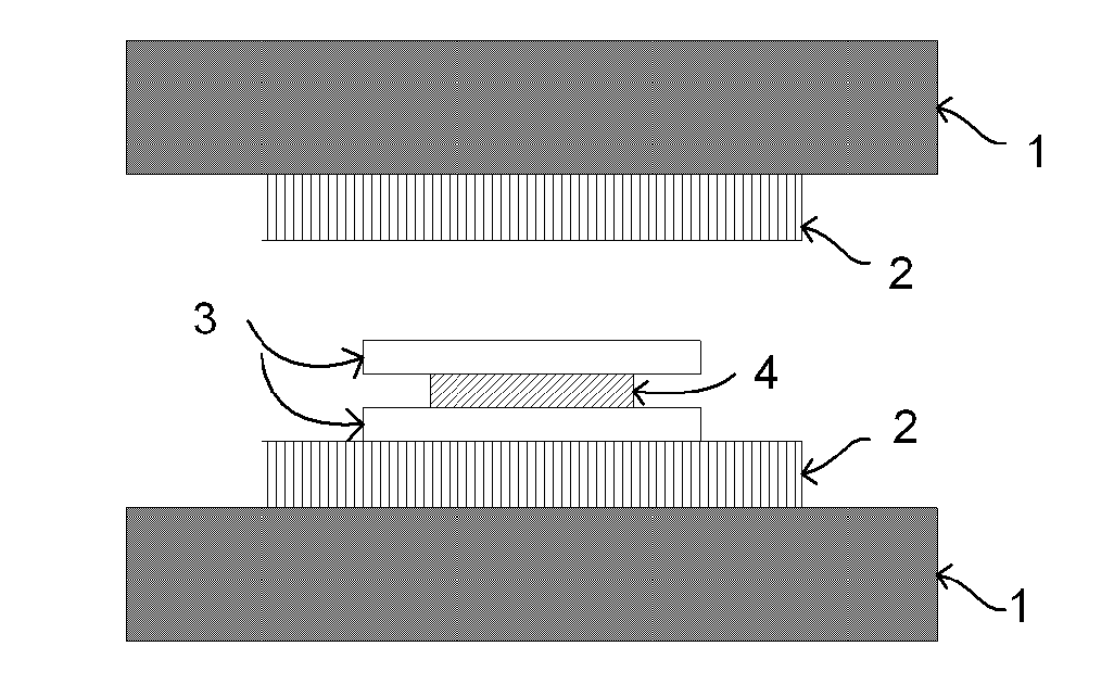
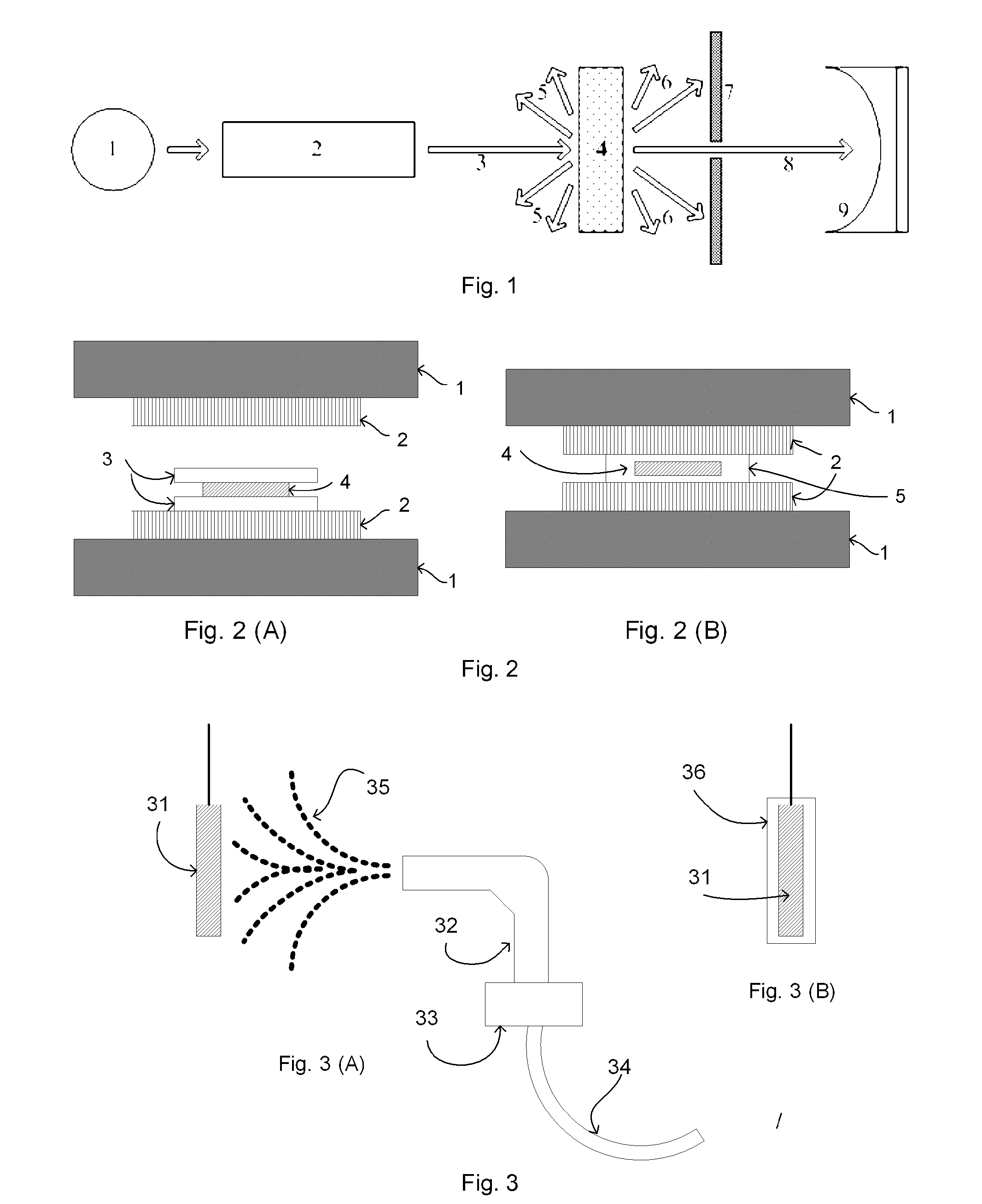
[0168]In a heating press, between two steel plates (1), a silicon-based photovoltaic element (4) was assembled with two portions (3) of the film obtained as described in example 2 and sandwiched between two sheets of PTFE (2), as depicted in FIG. 2(A). The photovoltaic element was previously pre-treated at 200° C. for at least 30 minutes in order to eliminate moisture and other contaminants from the silicon surface.
[0169]The so-obtained assembly, as depicted in FIG. 2(B), was submitted to the following thermal treatment
[0170]1) pre heating of the heating press at 250° C.;
[0171]2) introduction of the assembly in the heating press;
[0172]3) heating of the assembly from r.t. to 250° C. in around 2 minutes;
[0173]4) continuous heating at 250° C. of the assembly with no applied pressure;
[0174]5) during 190 sec, heating was pursued by alternatively applying a pressure of 2 bars for 5 seconds and releasing said pressure;
[0175]6) heating of the assembly under a pressure o...
[0178]The dry powder of the polymer prepared according to the example 1 was loaded in the reservoir (33) of an electrostatic gun (32), equipped with a compressed air supply (34). A photovoltaic element (31) was heated at 250° C., earthed and the fine powder of polymer of example 1 (35) was sprinkled on the surface of the heated thereon, as depicted in FIG. 3(A) so as to obtain a solar cell module (36) having a photovoltaic element encapsulated between a front layer on its light receiving surface side and a back layer, both made from polymer of example 1 here above.
[0179]The solar cell module was found to assure suitable protection to the photovoltaic element and consistent encapsulation of said element with no delamination phenomena.
PUM
Property
Measurement
Unit
Temperature
aaaaa
aaaaa
Temperature
aaaaa
aaaaa
Molality
aaaaa
aaaaa
Abstract
The present invention pertains to a solar cell module comprising at least one photovoltaic element encapsulated between a front layer on its light receiving surface side and a back layer, said front layer comprising at least one layer comprising a tetrafluoroethylene (TFE) polymer [polymer (F)], said polymer (F) comprising: recurring units derived from TFE; and from 15 to 25% wt of recurring units derived from at least one perfluoromonomer [monomer (CM)] chosen among: (i) perfluoroalkylvinylethers complying with formula CF2═CFORf1, in which Rf1 is a C1-C6 perfluoroalkyl, e.g. —CF3, —C2F5, —C3F7; and / or (ii) perfluoro-oxyalkylvinylethers complying with formula CF2═CFOX0, in which X0 is a C1-C12 perfluorooxyalkyl having one or more ether groups, like perfluoro-2-propoxy-propyl; and (iii) mixtures thereof. Still objects of the invention are a process for the manufacture of the solar cell module as above defined and its use for producing current to external sources, e.g. for powering a fixed-wing aircraft.
Description
TECHNICAL FIELD[0001]The invention pertains to a solar cell module comprising a fluoropolymer outer layer, to a process for the manufacture of said solar cell module, and to the use of the same.BACKGROUND ART[0002]In recent years, heating of the earth because of the so-called greenhouse effect due to an increase of atmospheric CO2 has been predicted. In view of this, there is an increased demand for means of power generation capable of providing clean energy without causing CO2 buildup. In this regard, nuclear power generation has been considered to be advantageous in view of not causing CO2 buildup. However, there are problems for nuclear power generation in that it unavoidably produces radioactive wastes which are harmful for living things and there is a probability that leakage of injurious radioactive materials from the nuclear power generation system will happen when the system is damaged. Therefore, there is an increased societal demand for early realization of a power generat...
Claims
Application Information
Patent Timeline
Application Date:The date an application was filed.
Publication Date:The date a patent or application was officially published.
First Publication Date:The earliest publication date of a patent with the same application number.
Issue Date:Publication date of the patent grant document.
PCT Entry Date:The Entry date of PCT National Phase.
Estimated Expiry Date:The statutory expiry date of a patent right according to the Patent Law, and it is the longest term of protection that the patent right can achieve without the termination of the patent right due to other reasons(Term extension factor has been taken into account ).
Invalid Date:Actual expiry date is based on effective date or publication date of legal transaction data of invalid patent.

