
Vinylidene fluoride copolymers

a technology of vinylidene fluoride and copolymer, which is applied in the direction of conductive materials, non-conductive materials with dispersed conductive materials, conductive materials, etc., can solve the problems of affecting the thermal stability of the copolymer itself, the final material's mechanical properties are impaired, and the copolymerization of vinylidene fluoride and hydrophilic (meth)acrylic monomers remains a difficult task, etc., to achiev

Active Publication Date: 2010-06-03
SOLVAY SOLEXIS
View PDF17 Cites 62 Cited by
  • Summary
  • Abstract
  • Description
  • Claims
  • Application Information

AI Technical Summary

Benefits of technology

[0020]The Applicant has found that the substantially random distribution of hydrophilic (meth)acrylic monomer (MA) within the polyvinylidene fluoride backbone of the polymer (A) advantageously maximizes the effects of the modifying monomer (MA) on both adhesiveness and / or hydrophilic behaviour of the resulting copolymer, even at low levels of hydrophilic (meth)acrylic monomer (MA) in the composition, without impairing the other outstanding properties of the vinylidene fluoride polymers, e.g. thermal stability and mechanical properties.
[0105]A good solvent for polymer (A) is particularly advantageous when the mixture (Mx) is processed by casting, as it can advantageously help in tuning the viscosity of said mixture (Mx).

Problems solved by technology

Often, these materials are produced by surface functionalization of pre-formed PVDF materials, so as to obtain grafted copolymers; nevertheless such grafted copolymers suffer from the drawback that as grafting is generally initiated via radical route, by providing free radicals generation on the fluorinated backbone: uncontrolled radical side reactions occur, yielding poorly soluble, generally cross-linked materials, and / or generating chains breaks, so that the final material possess impaired mechanical properties.
Copolymerizing vinylidene fluoride and hydrophilic (meth)acrylic monomer remains indeed an uneasy task, due to the very different reactivity of such copolymers and their intrinsic incompatibility.
This uneven distribution of the hydrophilic (meth)acrylic monomer units dramatically affects the thermal stability of the copolymer itself.
This problem has been found particularly critical in copolymers comprising lower amount of hydrophilic (meth)acrylic monomers, especially of acrylic acid, wherein the formation of blocky domains of concatenated acrylic acid substantially depletes the resulting copolymers of the targeted properties, so that no modification in adhesiveness is obtained.

Method used


Image

  • Vinylidene fluoride copolymers
  • Vinylidene fluoride copolymers
  • Vinylidene fluoride copolymers

Examples


example 1

[0123]In a 4 liter reactor equipped with an impeller running at a speed of 880 rpm were subsequently introduced the following ingredients:[0124]Demineralized water: 2473 g;[0125]Suspending agent: 0.8 g (Methocel® K100GR from DOW Chemical).

[0126]Reactor was then repeatedly evacuated and purged with nitrogen (1 bar) while maintaining the temperature at 14° C. Then 2 g of acrylic acid (AA) and then 3 g of a solution of the initiator t-amyl perpivalate in isododecane (75%) were introduced into the autoclave and immediately after, 1050 g of VDF monomer were introduced into the reactor. The reactor was then gradually heated until the set-point temperature of 52° C. was attained, which corresponded to a pressure of 120 bar. The pressure was kept constantly equal to 120 bar during the whole polymerization run by feeding an aqueous solution comprising 37 g of AA / I of solution. After 671 minutes the polymerization was stopped by degassing the suspension until reaching atmospheric pressure. A ...

example 2

[0128]Same procedure as detailed in example 1 was followed, but initially introducing in the reactor 1 g of acrylic acid (AA) and 1058 g of VDF monomer and continuously feeding an aqueous solution containing 18.5 g of AA / I of solution. Reaction was stopped after 528 minutes, after having fed a total of 700 ml of AA solution. Recovered amount of dry polymer was found to be 815 g. Composition and DSC properties of so obtained polymer are summarized in Table 1. Data regarding TGA analysis and thermal stability are summarized in Table 2.

example 4

Preparation of Electrode Comprising Polymer of Example 1

[0130]1 g of resin produced as in example 1 was dissolved in 50 g of N-methylpyrrolidone (NMP) under mechanical stirring at room temperature using a Dispermat device equipped with a flat PTFE disc. Under moderate stirring, 1.67 g of SuperP (conductive Carbon Black) and 30.67 g Lithium Cobaltum Oxide (LiCoO2) were added and the slurry was thoroughly mixed to ensure a good homogeneity. All the materials involved in the slurry preparation were previously conditioned either by drying using molecular sieve of 4 Å (for the solvent) or by heating for one night at 100° C. (for the powders). The solid concentration of the composition was 40% weight, polymer (A) representing 3% wt of the total solids components (polymer (A)+active material (carbon black 5% and Li Oxide 92%)). The composition was then degassed under vacuum and spread using a Doctor Blade coating instrument on an Aluminum foil, previously degreased. The coating was finally...


PUM

PropertyMeasurementUnit
temperatureaaaaaaaaaa

Abstract

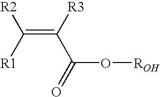
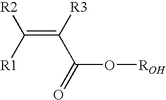
The present invention pertains to a linear semi-crystalline copolymer [polymer (A)] comprising recurring units derived from vinylidene fluoride (VDF) monomer and at least one hydrophilic (meth)acrylic monomer (MA) of formula (I) wherein each of R1, R2, R3, equal or different from each other, is independently an hydrogen atom or a C1-C3 hydrocarbon group, and ROH is a hydrogen or a C1-C5 hydrocarbon moiety comprising at least one hydroxyl group, said polymer (A) comprising from 0.05 to 10% by moles of recurring units derived from said hydrophilic (meth)acrylic monomer (MA) and being characterized by a fraction of randomly distributed units (MA) of at least 40%, having improved thermal stability, to a process for its manufacture, to a composition comprising the same, and to its use as binder in batteries or for the manufacture of hydrophilic membranes.

Description

TECHNICAL FIELD[0001]The present invention pertains to vinylidene fluoride copolymers comprising recurring units derived from hydrophilic (meth)acrylic monomers having improved thermal stability, to a process for their manufacture, to a composition comprising the same, and to their use as binder in batteries or for the manufacture of hydrophilic membranes.BACKGROUND ART[0002]Vinylidene fluoride (VDF) copolymers comprising recurring units derived from hydrophilic (meth)acrylic monomers (e.g. acrylic acid) are well known in the art.[0003]Such copolymers have been developed aiming at adding to the mechanical properties and chemical inertness of PVDF suitable adhesion towards metals, e.g. aluminium or copper, or hydrophilic properties.[0004]Often, these materials are produced by surface functionalization of pre-formed PVDF materials, so as to obtain grafted copolymers; nevertheless such grafted copolymers suffer from the drawback that as grafting is generally initiated via radical route...

Claims


Application Information

Patent Timeline
Patent Type & Authority Applications(United States)
IPC IPC(8): H01B1/24C08F214/22C08L27/16H01B1/20
CPCB01D69/02B01D71/34B01D2325/36C08F214/22B01D71/76C08J5/2237H01M4/621C08J2327/16B01D71/40C08F214/225Y02E60/10B01D71/401C08F220/18C08J5/18
Inventor ABUSLEME, JULIOPIERI, RICCARDOBARCHIESI, EMMA
Owner SOLVAY SOLEXIS
Learn More