Process for producing oxide crystal fine particles

Inactive Publication Date: 2010-06-24
ASAHI GLASS CO LTD
View PDF4 Cites 10 Cited by
  • Summary
  • Abstract
  • Description
  • Claims
  • Application Information

AI Technical Summary

Benefits of technology

[0016]By the process of the present invention, it is possible to selectively obtain fine particles which have a small particle diameter and which are excellent in uniformity of the particle diamete

Problems solved by technology

One of the most serious problems as such processing defects is formation of scratches.
However, there has still remained a problem such that when such particles are employed as abrasive grains, fine scratches are still formed which are considered to be attributable to the presence of coarse particles.
However, even when the method of Patent Document 3 is employed, de

Method used


Image

  • Process for producing oxide crystal fine particles

Examples


Example

Example 1

[0100]Cerium oxide (CeO2), barium carbonate (BaCO3) and boron oxide (B2O3) were weighed so that they will be 33.4%, 13.3% and 53.3%, respectively, as represented by mol % based on CeO2, BaO and B2O3, and thoroughly wet-mixed in an automatic mortar by means of a small amount of ethanol, followed by drying to obtain a starting material mixture.

[0101]The obtained starting material mixture was filled in a platinum container (containing 10 mass % of rhodium) provided with a nozzle for dropwise addition of a melt and heated at 1,500° C. for two hours in an electric furnace using molybdenum silicate as a heating element and completely melted (melting step). Then, the nozzle portion was heated, and the melt was dropped on twin rolls (roll diameter: 150 mm, roll rotational speed: 300 rpm, roll surface temperature: 30° C.) made of SUS316 installed below the electric furnace, to obtain a flake-form solid (rapid cooling step). The obtained flake-form solid was transparent and confirme...

Example

Example 2

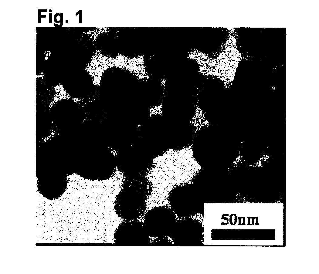
[0108]Fine particles of CeO2 crystal were obtained in the same manner as in Example 1 except that the time for heating the pulverized material was changed to 32 hours. The crystallite diameter of the obtained fine particles was 22 nm, the average primary particle diameter was 26 nm, crystallite diameter:average primary particle diameter=1:1.2, and the variation coefficient of the particle diameter was 0.22.

Example

Example 3

[0109]A starting material mixture was obtained in the same manner as in Example 1 except that the mixing proportions of cerium oxide (CeO2), calcium carbonate (CaCO3) and boron oxide (B2O3) were changed to 20.0%, 35.6% and 44.4%, respectively, as represented by mol % based on CeO2, CaO and B2O3.

[0110]To this starting material mixture, the melting step and the rapid cooling step were applied in the same manner as in Example 1 to obtain an amorphous material.

[0111]The obtained amorphous material was pulverized for 8 hours by a dry ball mill using zirconia balls with 5 mm in diameter to obtain a pulverized material. The volume-based particle size distribution of the obtained pulverized material was within a range of from 0.6 μm to 17 μm, and its D90 was 7.2 μm.

[0112]The obtained pulverized material was heated at 700° C. for two hours to precipitate CeO2 crystal.

[0113]Then, this powder made of crystal-precipitated particles was added to an acetic acid aqueous solution, followe...


PUM

PropertyMeasurementUnit
Temperatureaaaaaaaaaa
Fractionaaaaaaaaaa
Fractionaaaaaaaaaa

Abstract

To provide a process for producing fine particles of crystalline oxide which have high crystallinity, are excellent in uniformity of the composition and particle diameter, and have a small particle diameter, and such fine particles of crystalline oxide.
A process for producing fine particles of crystalline oxide, which comprises:
a step of obtaining a melt containing an oxide of M (M is at least one member selected from the group consisting of Ce, Ti, Zr, Al, Fe, Zn, Mn, Cu, Co, Ni, Bi, Pb, In, Sn and rare earth elements (excluding Ce)) and B2O3,
a step of rapidly cooling the melt to form an amorphous material,
a step of pulverizing the amorphous material to obtain a pulverized material having a volume-based particle size distribution within a range of from 0.1 to 40 μm,
a step of heating the pulverized material to precipitate an oxide crystal containing M in the pulverized particles, and
a step of separating components other than the oxide crystal containing M from the crystal-precipitated particles to obtain fine particles of crystalline oxide containing M, in this order.

Description

TECHNICAL FIELD[0001]The present invention relates to a process for producing fine particles of crystalline oxide, particularly to a process to easily obtain fine particles of crystalline oxide which have high crystallinity, are excellent in uniformity of the composition and particle diameter and have a small particle diameter, and such fine particles.BACKGROUND ART[0002]In recent years, particularly along with high integration / high functionality of semiconductor integrated circuits, it has been desired to develop microfabrication techniques for microsizing / high densification. In a process for producing semiconductor devices, particularly in a process for forming multilayer wirings, a technique for planarization of interlayer dielectric films or embedded wirings is important. That is, as wirings have become multi-layered to meet microsizing / high densification in the semiconductor production process, the surface irregularities at each layer tend to be large, and in order to prevent s...

Claims


Application Information

Patent Timeline
IPC IPC(8): C01F17/00B32B5/16C01F17/235
CPCB82Y30/00Y10T428/2982C01F17/0043C01G25/006C01P2002/50C01P2004/04C01P2004/32C01P2004/51C01P2004/61C01P2004/62C01P2004/64C01P2006/10C01P2006/12C01P2006/22C09K3/1409C09K3/1427C01P2002/60C01B13/14C01F17/235C01G25/02C01F17/224C01P2004/60
Inventor SAKAI, TOMOHIROBEPPU, YOSHIHISASUZUKI, HIROYUKIINUZUKA, NOBUO
Owner ASAHI GLASS CO LTD
Why Eureka
Try Eureka