Method of manufacturing transition metal oxide having spinel structure

Active Publication Date: 2010-08-05
NGK INSULATORS LTD
View PDF3 Cites 47 Cited by
  • Summary
  • Abstract
  • Description
  • Claims
  • Application Information

AI Technical Summary

Benefits of technology

[0016]According to the present invention, a new method of manufacturing a transition metal oxide having a spinel structure is provided. This method is a manufacturing process in which high strength is obtained through the heat treatment at a relatively low temperature, and moreover, variation in the strength is reduc

Problems solved by technology

Therefore, there is the possibility that the desired bonding strength is not obtained and a joining may be broken down during operation of the cell.
In addition, the contact resistance is large due to the insufficient sintering of the bonding agent.
However, there is a problem that the cost is high, since silver is expensive.
However, the inventors have found that th

Method used


Image

  • Method of manufacturing transition metal oxide having spinel structure
  • Method of manufacturing transition metal oxide having spinel structure
  • Method of manufacturing transition metal oxide having spinel structure

Examples


experiment 1

Evaluation of Bonding Strength

[0052]The bonding strength to the cell electrode of the conductive bonding agents in the inventive example and the comparative example was evaluated by using an assembly illustrated in FIGS. 3(a) and 3(b).

(Preparation of Bonding Paste)

[0053]Oxide powder of the transition metal 1 and that of the transition metal 2 were weighed according to a molar ratio shown in the Table 1, and mixed and pulverized in a pot mill for 24 hours to obtain slurry. The obtained slurry was dried by an oven at 80° C., and then sintered for 1 hour at 800° C. in the air atmosphere to synthesize the spinel type complex oxide. The synthesized spinel was pulverized in the pot mill again to obtain the complex oxide powder with an average particle diameter of 0.5 p.m. To this powder, ethyl cellulose as the binder and terpineol as the solvent were added to prepare the bonding paste.

[0054]Further, metal powder of the transition metal 1 and that of the transition metal 2 were weighed in ...

experiment 2

Power Generation Test

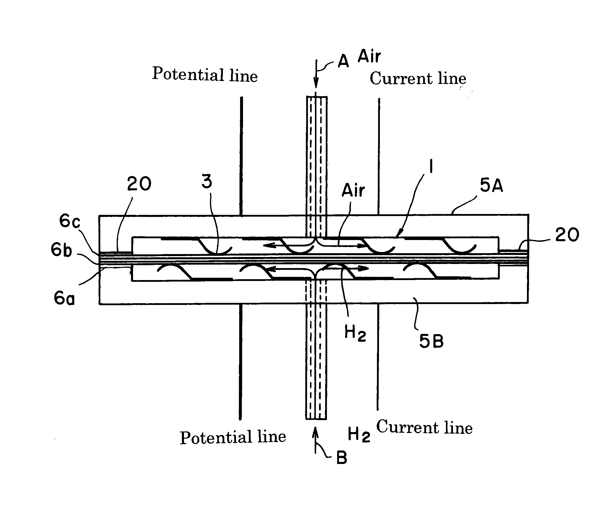
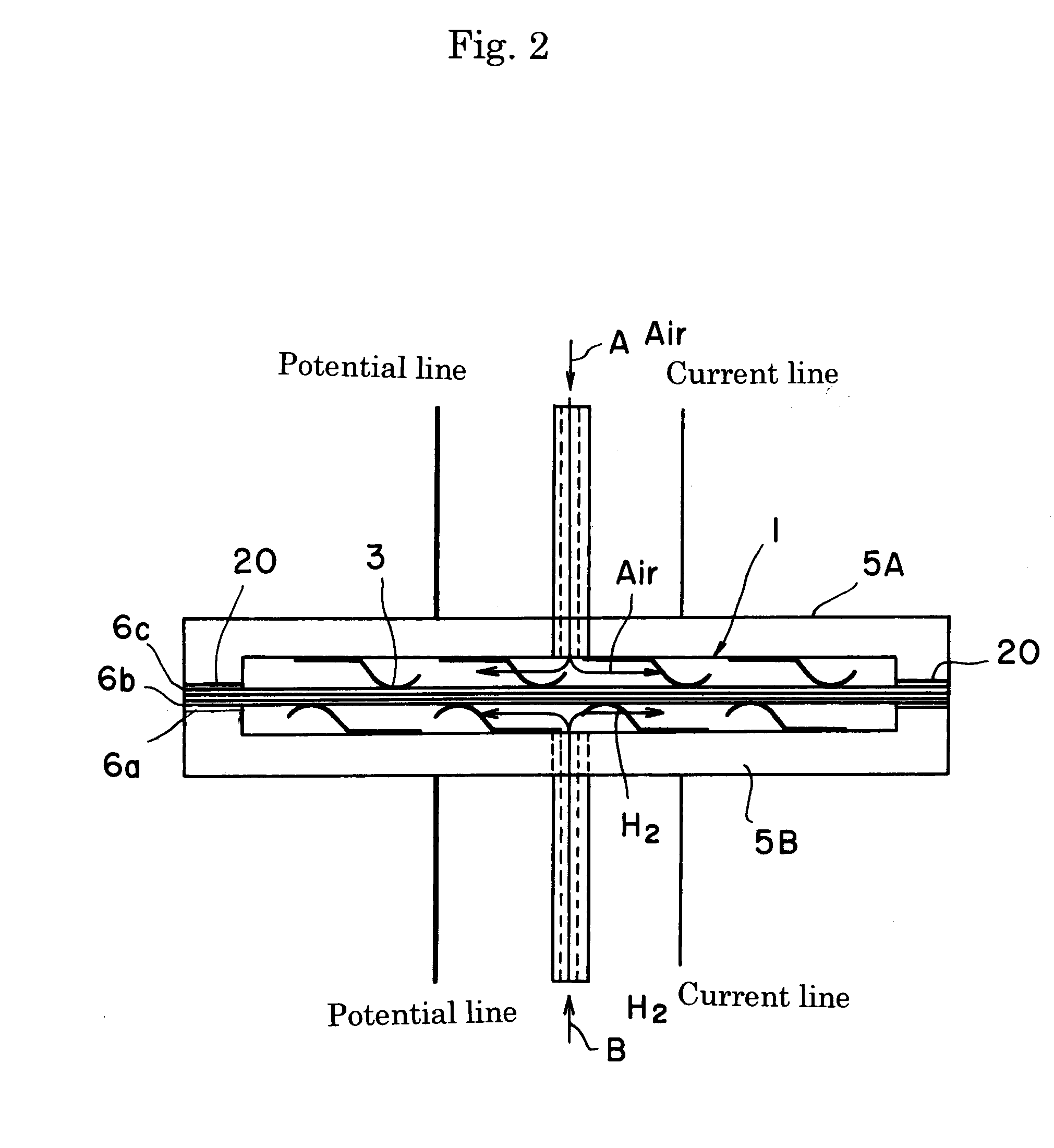
[0062]A solid oxide fuel cell using the fuel electrode as a substrate was prepared as schematically illustrated in FIG. 2.

(Preparation of Fuel Electrode Substrate)

[0063]50 parts by weight of nickel oxide powder having an average particle diameter of 1 μm and 50 parts by weight of yttria-stabilized zirconia powder (8YSZ, “TZ-8Y”: produced by Tosoh Corporation) were mixed, and polyvinyl alcohol (PVA) was added as the binder to prepare slurry. This slurry was dried and granulated with a spray drier to obtain powder for fuel electrode substrate. The granulated powder was molded by a metal mold pressing method to obtain a disk having a diameter of 120 mm and a thickness of 1.5 mm. Thereafter, the disk was sintered for 3 hours at 1400° C. in air in an electric furnace to obtain a fuel electrode substrate 6a.

(Formation of Solid Electrolyte Film)

[0064]Water and the binder were added to 8 mol % yttria-stabilized zirconia powder, and mixed in a ball mill for 16 hours. Th...

experiment 3

Average Particle Diameter and Characteristics of Material Metal Powder

[0072]In this experiment, an investigation relating to average particle diameters of Mn metal powder and Co metal powder was performed in the case of MnCo2O4.

[0073]As shown in the Table 3, the bonding agent was adjusted by combining various particle diameters so as to have a spinel composition.

[0074]Specifically, particle diameters of the metal manganese powder and the cobalt powder were changed as shown in the Table 3. The manganese powder and the cobalt powder were mixed in a molar ratio of 1:2. To this mixed powder, ethyl cellulose as the binder and terpineol as the solvent were added, and the added powder was mixed using a mortar to prepare the paste. This paste was dried for 1 hour at 100° C. Thereafter, the paste was sintered for 1 hour at 900° C. in air.

[0075]The paste of each example was applied to a surface of the air electrode 6c on the air electrode disk 11 and a surface of the metal disk 10 prepared in...


PUM

PropertyMeasurementUnit
Particle diameteraaaaaaaaaa
Pressureaaaaaaaaaa
Pressureaaaaaaaaaa

Abstract

A novel method of manufacturing a transition metal oxide having a spinel structure is provided. A mixture of powdery metals of metal elements constituting the transition metal oxide is heated in an oxidizing atmosphere to generate the transition metal oxide.

Description

[0001]This application claims the benefits of Japanese Patent Applications P2009-23956 filed on Feb. 4, 2009 and P2009-204489 filed on Sep. 4, 2009, the entireties of which are incorporated by reference.TECHNICAL FIELD[0002]The present invention relates to a method of manufacturing a transition metal oxide having a spinel structure.BACKGROUND ARTS[0003]To produce a solid electrolyte fuel cell stack structure by stacking separators and electrochemical cells alternately, it is necessary to supply a gas between the separator and the single cell so that fuel or oxidizing agent is supplied to electrodes of the single cell. At the same time, the single cell and the separator must be electrically connected in series by inserting a conductive connecting member (interconnector) between the separator and the single cell. When the above-described conductive connecting member is located in, for example, a fuel gas passage, it must be chemically stable in a reductive fuel gas at an operating tem...

Claims


Application Information

Patent Timeline
IPC IPC(8): B32B37/24C23C8/10
CPCC01G45/1235Y02E60/525C01G45/1264C01G49/0063C01G51/40C01G53/00C01G53/40C01P2002/32C01P2002/52C01P2004/61C01P2004/62C01P2006/40H01M8/0282H01M8/0286H01M8/0297H01M2008/1293C01G49/0018C01G49/009C01G51/006C01G51/68Y02E60/50C01G45/1242Y02P70/50
Inventor RYU, TAKASHINAKAMURA, TOSHIYUKIOHMORI, MAKOTO
Owner NGK INSULATORS LTD
Why Eureka
Try Eureka