
Remotely reconfigurable system for mapping subsurface geological anomalies

a remote reconfigurable system and geological anomaly technology, applied in the direction of instruments, nuclear elements, using reradiation, etc., can solve the problems of reducing the resistance to tensile forces and vibration, prone to cracking of slab-on-grade foundations, and extraordinary resistance to compressive forces of typical concrete, so as to achieve the effect of not requiring excessive downtim

Active Publication Date: 2010-08-05
EARTHSYST TEHNOLOGIES INC
View PDF25 Cites 17 Cited by
  • Summary
  • Abstract
  • Description
  • Claims
  • Application Information

AI Technical Summary

Benefits of technology

[0025]Soil, rocks, and vegetative matter can conduct electricity to varying degrees. The resistance, or resistivity, of these materials to an electrical current will vary depending upon density, particle composition, moisture content, and the chemical composition of fluid in the spaces between the particles. A fluid leak from, for example, pipes in a slab or a waste conduit or water main under a paved roadway into the subjacent soil will affect the electrical resistivity (resistance offered by a material to the flow of electrical current, multiplied by the cross-sectional area of current flow and per length of current path). Fluid generally decreases the resistivity of the subgrade. Measuring resistivity at varying depths and at varying locations, both beneath and adjacent to a slab foundation or paved roadway, and comparing these resistivities to one another, allows one the location of soil anomalies based on resistivity variations. These anomalies can include wet soil, vegetative matter and buried metallic and non-metallic objects. Research has shown that the location of resistivity anomalies corresponds well to the location of soil anomalies.
[0027]The preferred embodiment contemplates converting the measured potential to a resistivity value, assigning the resistivity value to a spatial coordinate, and storing these values in a computer file. A computer program then performs a least squares data inversion analysis on the resistivity and location values, creating an electrical resistivity model that minimizes the error of the field data. Next, another computer program performs a spatial data analysis, or geostatistical analysis, using kriging or other methods.
[0029]The preferred embodiment provides for an apparatus and method for controlling the amplitude of injected current with a power distribution unit, the current being ramped up and down during the sequence of geophysical test in order to preserve power source battery charge and to ensure like current and voltage conditions for each measurement. The preferred embodiment of the power distribution unit also causes voltage control unit operating power to be drawn from stored capacitive energy alone during a measurement for creating minimal electrical noise in the system. A novel design for a solid state relay switch is taught whereby the injected current is connected through at least two electrodes in such a way as to avoid the need to draw system power during the measurement and whereby the measurement noise is reduced over prior art methods.
[0032]In the event of damage to a sensor or damage to an interconnecting cable, a replacement sensor or cable may be added to the array of sensors without excessive downtime and expensive field repairs because all of the sensors are identical. The replacement sensor can unambiguously identify itself with respect to other sensors to the control processor for use by the mapping software.

Problems solved by technology

Typical concrete exhibits extraordinary resistance to compressive forces but lower resistance to tensile forces and vibration.
Slab-on-grade foundations are typically prone to cracking due to defication when the subgrade becomes unstable.
In this case, detecting subsurface anomalies is a difficult task because limited time and resources often prevents a sufficient sample size to be adequately confident that the site located is free from anomalies or subsurface fluid flow.
Detecting and locating fluid leaks and other subsurface anomalies beneath composite concrete and asphalt structures is often a difficult task because the concrete or asphalt prevents access to the soil underneath.
Methods of the prior art often require destruction of large sections of the composite structures to locate leaks and other subsurface anomalies because the exact location of the leak or anomaly is unknown.
However, because the potentially leaking fluid must be driven to a potential, mise-a-la-masse methods can monitor for leaks in continuous fluid systems only, such as ponds, lined fluid containment areas, and tanks.
However, Daily does not disclose a method or apparatus that allows the electrodes to be placed directly under the leak source, after construction of a structure or paved roadway.
However, Henderson '045 does not disclose a method of directly monitoring the subgrade beneath a structure without permanently burying the electrodes or a method to place electrodes beneath an existing structure.
First, it requires an electrically conductive fluid container.
Second, it requires that the electrodes be permanently buried in the soil surrounding the tank.
Finally, it requires the use of an AC generator, which is less convenient than a DC power source.
However, Bryant does not disclose the ability to switch current between nodes or to conduct an orderly permutation of voltage measurements between nodes.
None of the prior art is entirely satisfactory to locate fluid leaks beneath composite and reinforced concrete structures or to analyze them in near real time.
For instance, it is not practical to electrify the potentially leaking fluid and because there may exist multiple sources of fluid, mise-a-la-masse is not a practical option.
Nor is it practical to embed permanently a series of electrodes beneath an existing massive concrete structure or roadway to monitor soil resistivity.
Further, because some of the ERT methods use multiple-plate electrodes where a large hole is bored to insert the electrodes into the subjacent soil making the method impractical and destructive.
In addition, placing the electrodes around the periphery of a roadbed or foundation is less accurate compared to placing the electrodes directly beneath or adjacent the potential leak source.
The current state of the art is unsatisfactory because it does not provide a method to remotely change injection current locations or to conduct an orderly progression through a permutation of voltages and currents between nodes.
Moreover, the state of the art does not provide for dynamically addressable sensors whose location and address can be changed on the fly.
Furthermore, the present state of the art requires that the electrodes be placed in a linear, regularly spaced grid pattern that does not provide needed flexibility in the physical layout of arrays of electrodes in multiple, non-linear arrangements.
Furthermore, the prior art does not provide for a means to easily adjust an array of electrodes to avoid encapsulated steel structures such as rebar.
The requirement of physically measuring and placing electrodes is hampered by structures which include buildings, medians, or other obstructions which makes placing the electrodes accurately difficult.
The inaccurate placement of electrodes leads to errors in the mathematical calculations required to analyze the locations of the anomalies and therefore reduces the overall efficiency and accuracy of the system.
Moreover, the state of the art does not provide for interchangeability of sensors.
This limitation requires extensive time in installation and replacement of defective sensors.

Method used


Image

  • Remotely reconfigurable system for mapping subsurface geological anomalies
  • Remotely reconfigurable system for mapping subsurface geological anomalies
  • Remotely reconfigurable system for mapping subsurface geological anomalies

Examples


Embodiment Construction

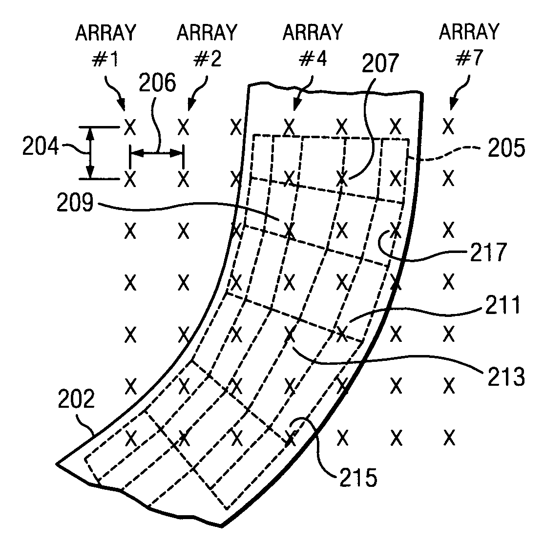
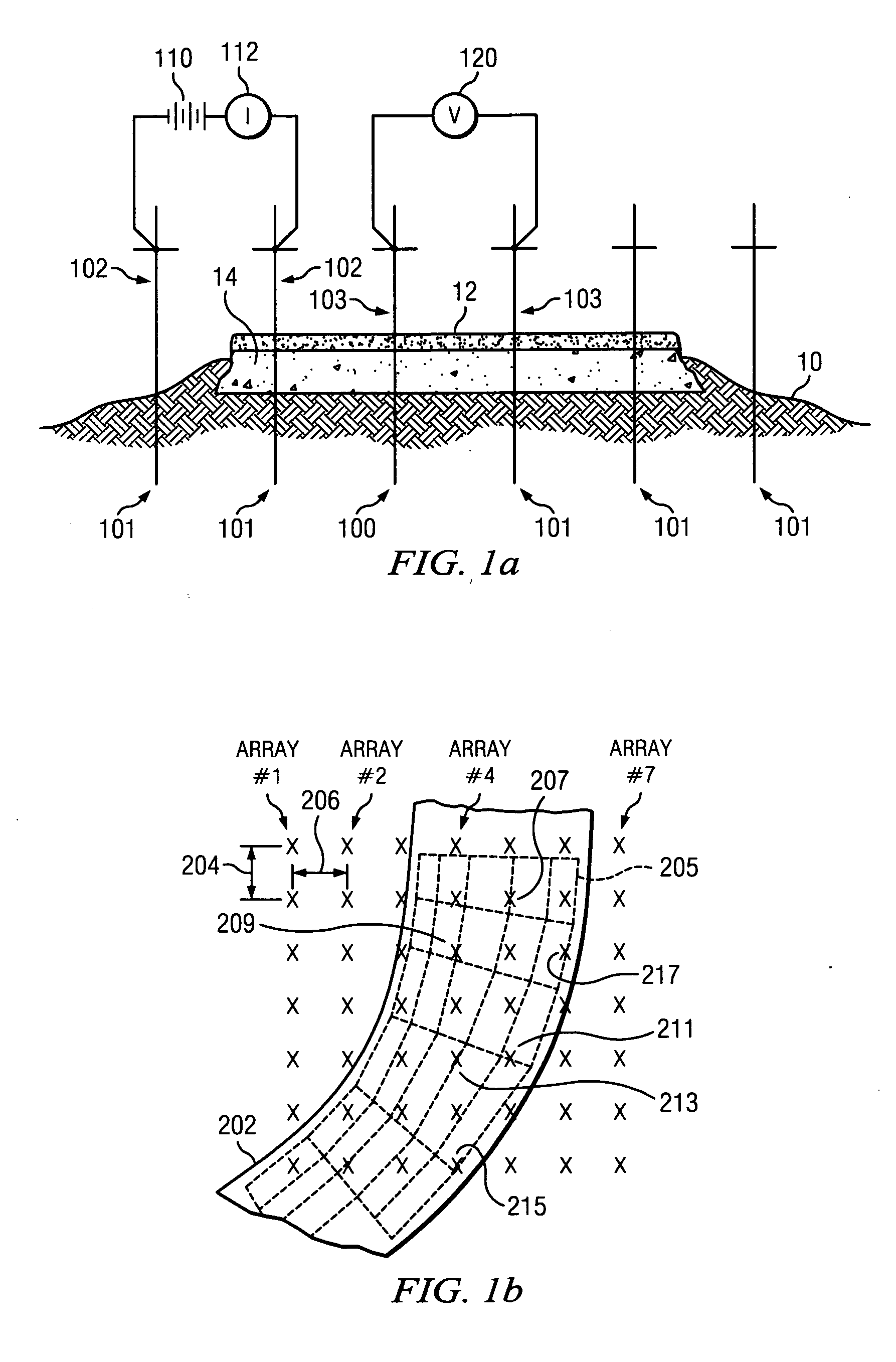
[0066]A schematic diagram of the theory used to gather data as used in the preferred embodiment is shown in FIG. 1a. A series of electrodes 101 are inserted, typically in a line, into ground 10. FIG. 1 shows the preferred embodiment as applied to an asphalt paved roadway. Asphalt layer 12 is applied on top of mid-level layer 14. Adhering to typical road construction principles, mid-level layer 14 may be a layer of concrete, steel reinforced concrete, or a compacted layer of gravel. In some situations, asphalt layer 12 may not be present. Electrodes 101 are inserted through both asphalt layer 12 and mid-level layer 14 and into ground 10 in order to determine resistivity and to map and detect subsurface soil anomalies under the roadway. The locations of electrodes 101 are typically in a regular pattern with a known interstitial distance between each electrode. In most situations, the known interstitial distance ranges from 6 to 10 feet and an equal interstitial distance is used betwee...


PUM


Abstract

A method and apparatus are provided for detecting and transmitting geophysical data from a plurality of electrodes inserted into the soil utilizing a set of identical dynamically reconfigurable voltage control units located on each electrode and connected together by a communications and power cable. A test sequence is provided in each voltage control unit. Each voltage control unit records data measurements for transmission to a central data collector. Each voltage control unit incorporates and determines its positional relationship to other voltage control units by logging when the unit is attached to the electrode. Each voltage control unit I equipped with a magnetic switch for detecting when they are in contact with the electrode.

Description

[0001]This application is a Continuation-In-Part claiming priority benefit from U.S. patent application Ser. No. 11 / 472,901 which was filed on Jun. 22, 2006 and from U.S. patent application Ser. No. 11 / 982,484 which was filed on Nov. 1, 2007.TECHNICAL FIELD OF THE INVENTION[0002]This preferred embodiment relates to a method for producing a subsurface electrical resistivity model. More specifically, the preferred embodiment relates to a method for resistivity modeling for locating anomalies, such as groundwater, leaks, tree roots, and other vegetation, particularly beneath and around existing composite concrete structures and roadbeds. Raw resistivity data is collected by a reconfigurable network of sensors that distributes current and measures voltage. A regression correlation is performed on the raw resistivity data to create a resistivity model, which is converted to graphical form, then analyzed to detect and locate subsurface soil anomalies.BACKGROUND OF THE INVENTION[0003]Moder...

Claims


Application Information

Patent Timeline
IPC IPC(8): G01V3/02
CPCG01V3/04G01V1/22
Inventor BRYANT, JOHNWILLEY, H. MICHAELLEHMANN, GUENTER H.SALAMAT, ARASH TOMEDGAR, MICHAELLEOPOLD, JERRY
Owner EARTHSYST TEHNOLOGIES INC
Learn More