
Separation membrane for direct liquid fuel type fuel cell & production method thereof

a technology of separation membrane and fuel cell, which is applied in the direction of cell components, final product manufacturing, sustainable manufacturing/processing, etc., can solve the problems of difficult to obtain acceptablely difficult to obtain high fuel cell output, and inferior density of separation membrane, so as to improve the activity of electrode catalyst, improve the activity of heat resistance, and generate power stably

Inactive Publication Date: 2010-11-04
TOKUYAMA CORP
View PDF4 Cites 14 Cited by
  • Summary
  • Abstract
  • Description
  • Claims
  • Application Information

AI Technical Summary

Benefits of technology

The present invention proposes an anion-exchange membrane for a direct liquid fuel type fuel cell that addresses the problems of reduced membrane density, insufficient permeability of liquid fuel, and high film resistance. The membrane is produced using a specific polymerizable composition and a cross-linked anion-exchange resin with improved heat resistance. The membrane has a porous film as its base material, and the void portion of the film is filled with cross-linked anion-exchange resin. The membrane has a uniformity index of 30% or less, indicating its uniformity. The invention aims to improve the fuel cell output and performance by improving the heat resistance of the membrane while maintaining its density and permeability.

Problems solved by technology

As mentioned before, it has been a big problem in a separation membrane for a direct liquid fuel type fuel cell using an anion-exchange membrane to improve heat resistance to obtain a high-power fuel cell, able to generate power at a high temperature.
Namely, this separation membrane was inferior in denseness, and permeability of liquid fuel, i.e. the above-mentioned problem (iv), was not sufficiently reduced as expected, so that it was difficult to obtain acceptably high fuel cell output as a result.
In these cases, it was unavoidable to greatly increase film resistance contrary to the above improved property, causing difficulty to obtain high fuel cell output.
However, in the above case of using the bromoalkyl styrene instead of chloromethylstyrene, the reduction was further more drastic and severe.
Thus-foamed membrane shows significant asperity on its surface to hardly form an electrode thereon, and even when an electrode can be formed, the electrode may be peeled off by curling or getting wrinkles (to cause large deformation) of the membrane due to moistening by water since an amount of resin filled in a pore of the base material varies, so that it can no longer be used as a separation membrane for a fuel cell.

Method used


Image

  • Separation membrane for direct liquid fuel type fuel cell & production method thereof
  • Separation membrane for direct liquid fuel type fuel cell & production method thereof
  • Separation membrane for direct liquid fuel type fuel cell & production method thereof

Examples


example

[0119]Hereinafter, examples are taken to describe the present invention further in detail, but the present invention is not limited to these examples.

[0120]Note that each measurement method of various properties used for property evaluation of a fuel cell membrane in Examples and Comparative Examples, such as anion exchange capacity, moisture content, film resistance, durability of an anion-exchange group, methanol permeability and fuel cell output voltage, will be explained below.

[0121]1) Anion Exchange Capacity and Moisture Content

[0122]The anion-exchange membrane was dipped into 0.5 mol·L−1-NaCl aqueous solution for 10 hours or more to change it into a chloride ion type, followed by changing it further into a nitrate ion type with 0.2 mol·L−1-NaNO3 aqueous solution to generate a free chloride ion. The free chloride ion was titrated with silver nitrate aqueous solution by potentiometric titrator (COMTITE-900 by Hiranuma Sangyo Co., Ltd.) (A mol). Next, the same ion exchange membra...

examples 1 to 7

[0148]According to the composition shown in Table 1, respective kinds of monomers, etc. were mixed to obtain a polymerizable composition. 400 g of the obtained polymerizable composition was placed in a 500-ml glass container, and porous film shown in Table 1 was cut into a sample of 20 cm×20 cm to dip into the above polymerizable composition in the container.

[0149]Then, the porous film was taken out of the polymerizable composition, and both sides of the porous film were covered with 100-μm polyester films as separating material, followed by heating to polymerize under a pressure by 0.3 MPa nitrogen at the temperature shown in Table 1 for 5 hours.

[0150]The obtained membrane-shaped material was dipped into aqueous solution containing 6 weight % of trimethyl amine and 25 weight % of acetone at room temperature for 16 hours, and then suspended in large excess of 0.5 mol·L−1-NaOH aqueous solution for ion exchange of its counterion from bromide ion to hydroxide ion, followed by washing i...


PUM

PropertyMeasurementUnit
weightaaaaaaaaaa
resistanceaaaaaaaaaa
AC impedance methodaaaaaaaaaa

Abstract

Disclosed is a separation membrane for direct liquid fuel cells, which is composed of a quaternary ammonium-type anion exchange membrane. The quaternary ammonium-type anion exchange membrane is produced as follows: a polymerizable composition containing a styrene having a haloalkyl group, a crosslinking polymerizable monomer, a compound having an epoxy group and an effective amount of a polymerization initiator is brought into contact with a porous film, so that the pores of the porous film are filled with the polymerizable composition that is then polymerized therein; then a quaternary ammonium group is introduced into the bromoalkyl group; and then the counter ion of the quaternary ammonium group is ion-exchanged into a hydroxide ion. Also disclosed is a method for producing the quaternary ammonium-type anion exchange membrane.

Description

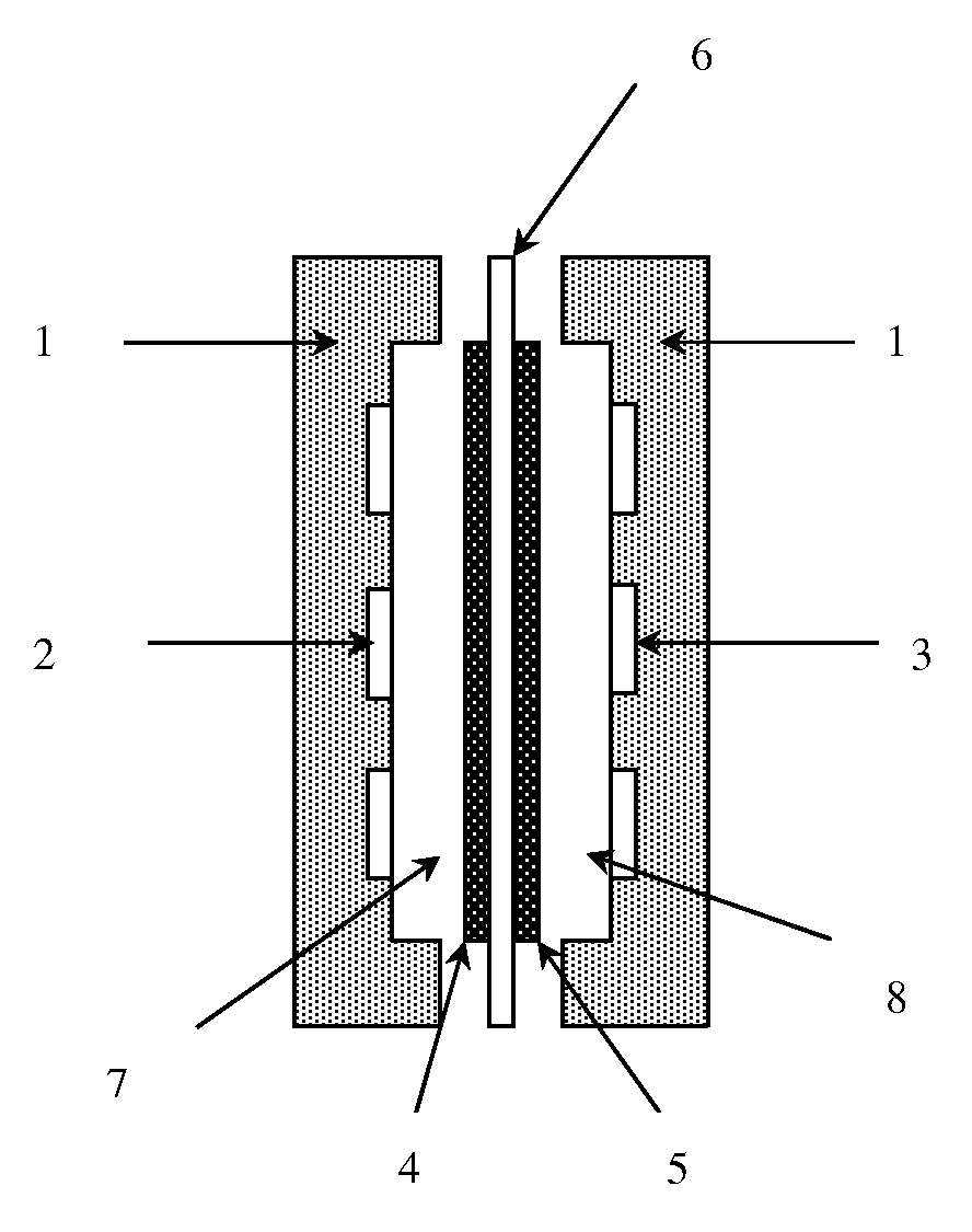
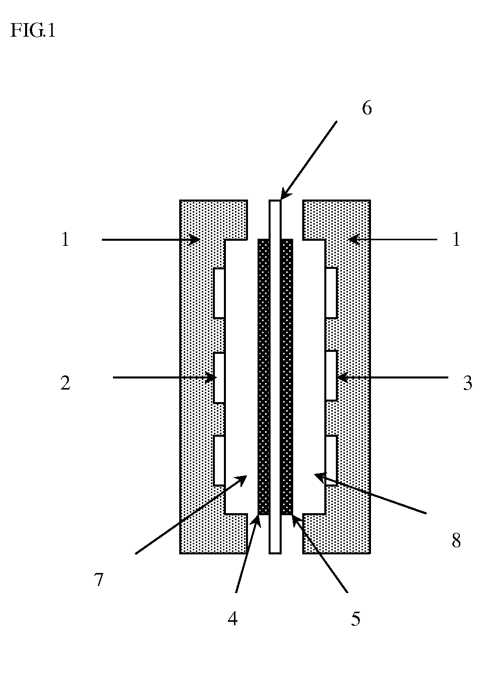
TECHNICAL FIELD[0001]The present invention relates to a separation membrane for a direct liquid fuel type fuel cell and production method thereof, specifically a separation membrane for a direct liquid fuel type fuel cell comprising anion-exchange membrane and production method thereof.DESCRIPTION OF THE RELATED ART[0002]A solid polymer type fuel cell uses solid polymer such as ion-exchange resin as an electrolyte, and is characterized by relatively low operating temperature. The solid polymer type fuel cell has, as shown in FIG. 1, a basic structure wherein a space surrounded by cell bulkhead 1 having a fuel flow hole 2 and oxidizing gas flow hole 3, respectively communicated with outside, is divided by a membrane assembly in which a fuel chamber side diffusion electrode 4 and an oxidizing agent chamber side gas diffusion electrode 5 are bonded to both surfaces of a solid polymer electrolyte membrane 6 respectively, to form a fuel chamber 7 communicated with outside via the fuel fl...

Claims


Application Information

Patent Timeline
Patent Type & Authority Applications(United States)
IPC IPC(8): H01M8/08H01M8/00
CPCC08J5/2275C09D125/18C08J2323/06H01B1/122H01M8/1009H01M8/1023H01M8/1039H01M8/1058H01M8/1067H01M2300/0082H01M2300/0091Y02E60/523C08J2365/02C08J9/405C08F212/08C08F12/26C08F12/14C08F212/14C08F8/32C08F8/44C08F212/26C08F212/28Y02P70/50Y02E60/50C08F212/18C08F212/36
Inventor ISOMURA, TAKENORIFUKUTA, KENJIYANAGI, HIROYUKI
Owner TOKUYAMA CORP
Learn More