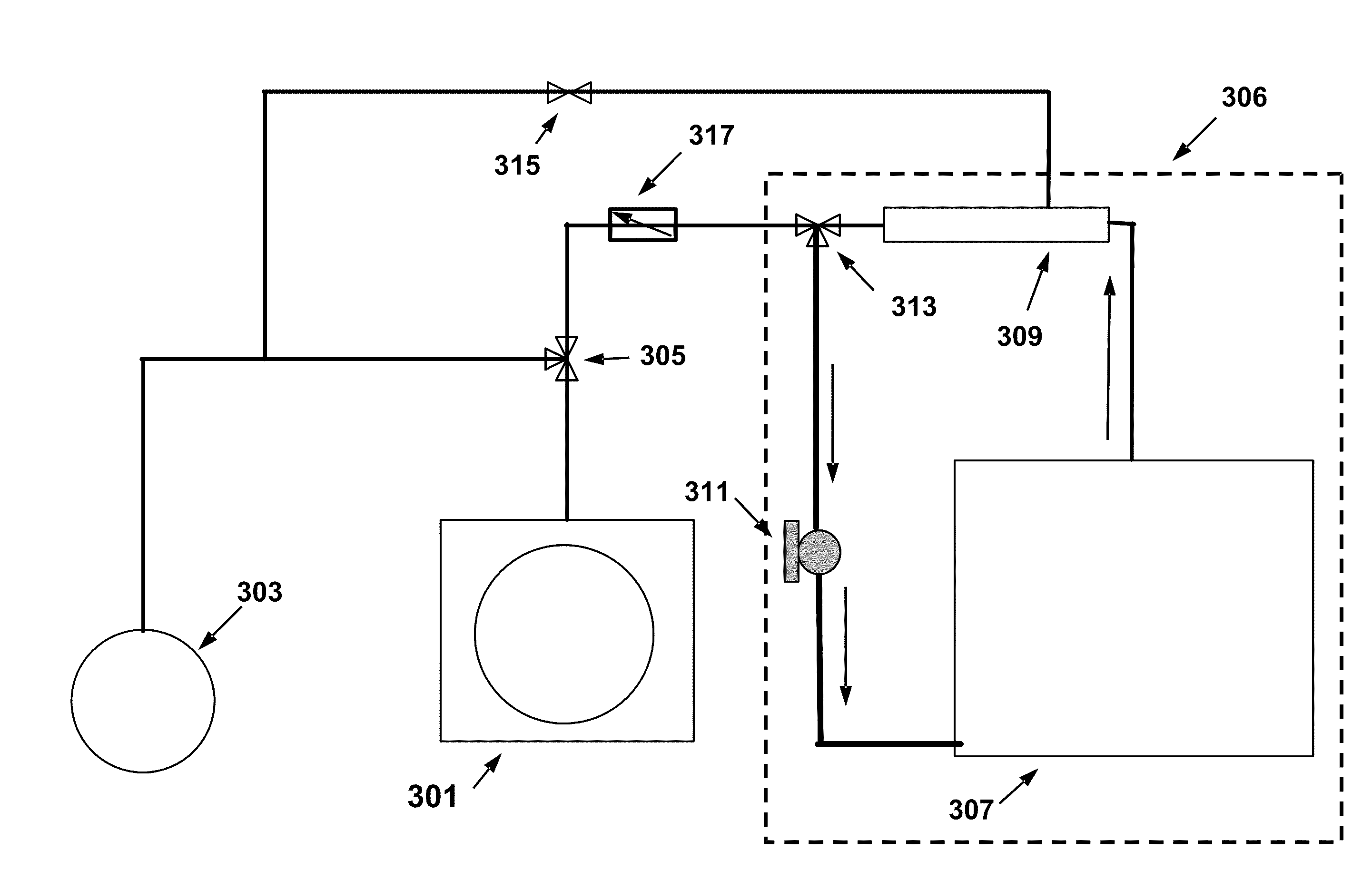
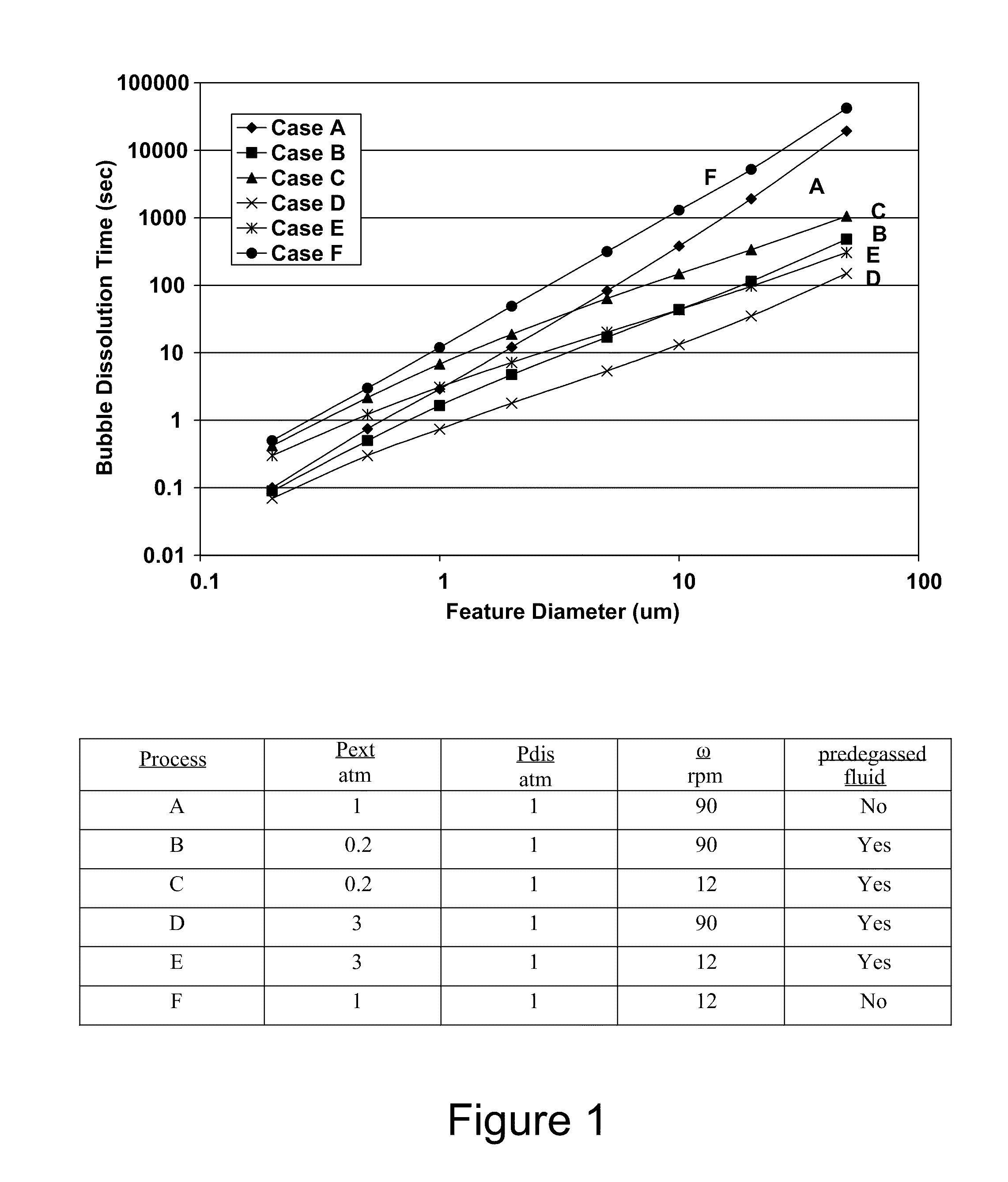
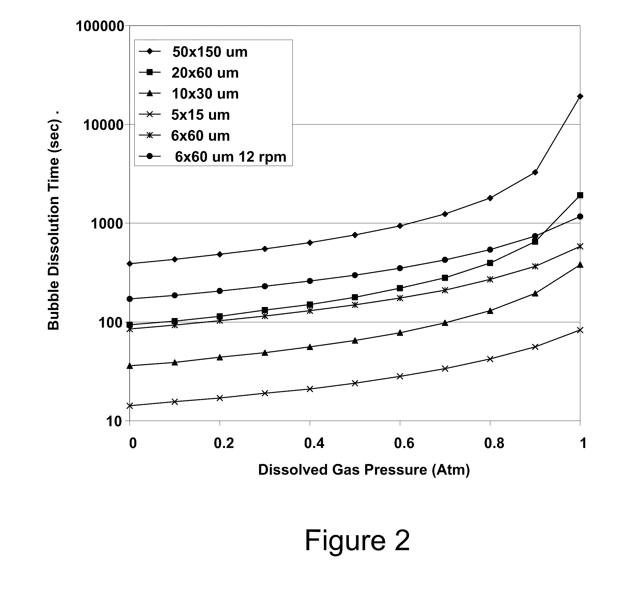
However, both of the favorable factors (i.e., high
internal pressure and short
diffusion distances) are missing in large TSV scale structures.
Even if this feature were only filled 10% with gas at its bottom, it would still take 20 minutes or more for that gas to be removed.
This procedure at first may appear to be appealing, but may suffer from two limitations.
Second, since the amount of gas in the solution can never be less than zero, the magnitude of the driving force for
dissolution is limited to be no more than approximately HxiP (P=1
atmosphere).
However, for a variety of reasons, including the
hardware complexity of combining plating processes with vacuum processes, pre-wetting (including vacuum feature-backfilled pre-wetting) is often performed in a different
cell, sub-
cell, or module than the plating
cell.
Furthermore, when using a pre-wetting fluid of a different composition than the plating bath, performing the pre-wetting process in the same module without enabling suitable mechanisms of removing and recovering excess entrained pre-wetting fluid that would be added to the plating solution would generally require mechanisms for mitigating, monitoring and / or otherwise correcting for plating solution modification over time.
This results in bubbles forming inside the vias.
While not wanting to be limited by a particular model or theory, a via bottom is a location of negative curvature, and it is believed that this location is a particularly susceptible to nucleating a bubble and releasing gas from the pre-wetting fluid.
The bubbles so formed can remain there after the pre-wetting process, which in turn can inhibit plating there and lead to associated defects.
If a separate pre-wetting chamber and apparatus are employed, but the pre-wetting fluid is not degassed, then intermittent and unreliable filling results may be observed.
Weeping can be a particularly difficult problem when dealing with salt containing pre-wetting fluids, because weeping salt laden fluids tend to dry and destroy the pores of the degassing device.
Also, reducing the temperature of the pre-wetting fluid reduces the rate of
metal corrosion in the pre-wetting
system.
This is because pressure can be transmitted to the bubble by a purely hydrostatic mechanism, and alternatively, application of
pneumatic pressure will not quickly re-saturate the pre-wetting fluid around a bubble in a via with gas because of the relatively long
diffusion distances involved.
Typically a 100 μm deep via might have a 25 μm
diameter opening, so the assumption of a bubble rising in an infinite media is not correct, as wall flow-slip effects will increase the time.
If the
wetting layer pulls back or coagulates from a previously wetted surface, then the attributes of the pre-wetting process are lost.
This de-wetting may cause the fluid to be drawn out from within any recessed features within the wafer substrate, possibly leading to gas being trapped within the feature on immersion into the plating bath.
Hydrophobic surfaces, particularly those that have completely de-wetted in some regions, have non-uniform fluid pre-
wetting layer thickness over the wafer substrate.
In the case that the pre-wetting fluid in use has a different composition than the plating bath, the subsequent immersion of the pre-wetted wafer into the plating solution will not allow for a uniformly wetted surface if the pre-wetting fluid has not wetted the wafer properly.
This can lead to variation in feature filling behavior or the creation of various wafer surface defects, such as lines of entrapped bubbles,
metal pits, metal thickness variations, or growth protrusions.
Furthermore, this transformation, specifically when occurring under vacuum and with a degassed pre-wetting fluid, leads to particularly favorable low defectivity when combined with the subsequent plating operation.
Furthermore, areas around state 3 that are in state 1 or 2 are wetted and are or will become hydrophilic, allowing fluid to flow freely and continuously over this surface and making the removal of the bubble or wetting of adjacent surfaces considerably more difficult.
Furthermore, bubble flushing is not 100% effective, and will often lead to bubble fragmentation, leaving a large number of smaller, hard to remove bubble behind.
Alkaline copper
cyanide and copper
pyrophosphate baths have also been widely used, with
cyanide baths having generally good plating performance, but have fallen out of favor for
toxicity and stability reasons.
During the ensuing time between the initial
exposure of the surface to the plating solution and the
initiation of plating, various unfavorable reactions with the constituents of the pre-wetting fluid, either alone, or in combination with gasses, coming from the
atmosphere, may occur.
Still, if and when the liquid
surface layer of the pre-wetted wafer is exposed to air, gas re-adsorption into the degassed pre-wetting fluid will occur (e.g., after 15 seconds or more), and may lead to deleterious
corrosion or other effects.
An example of a particularly deleterious reaction is the
corrosion reaction of the metal seed layer.
One such conceptually negative factor is that the
conductivity of such a pre-wetting fluid is quite small.
At the time immediately after immersion of a wafer into a plating bath solution, deposition at the bottom of the feature filled with a non-conductive or low
conductivity solvent is expected to be hindered by the inability to support plating because of its inability to support ionic current flow.
Another potentially detrimental factor is the formation, after entry of a wafer into an
electroplating bath, of a potential and the establishment of an internal corrosion cell due to the different activities of dissolved metals at the wafer surface and within the feature.
A
suppressor without the adsorption and electrochemical activity enhancing halides appears to be unfavorable, in some embodiments, unless at very low concentrations.
However, when a seed layer is marginal (e.g., rough and thin within the feature), such a pre-wetting fluid (i.e., the same or very similar to the plating solution) may be susceptible to feature fill voiding due to seed corrosion from the pre-wetting fluid.
For a wafer prepared and processed in exactly the same fashion, except that there was 3 minutes
exposure to atmospheric between release of vacuum and the
initiation of plating, the feature filling was grossly incomplete.
Therefore, the use of the plating solution as a pre-treatment solution is less than optimal in some embodiments because of its significant sensitivity to incomplete feature filling due to side wall corrosion.
Under such acidic conditions, the metal at the bottom of the feature's wall 1308 (FIG. 13) is subject to unfavorable conditions and could potentially result in the area corroding and producing a side wall without an electroplateable seed layer.
The combination of the
high conductivity, acidity, and potentially unfavorable adsorption and reaction of additives and
halide(s) with the metal can lead to, for example, feature sidewall corrosion and filling defects, as well as inhibiting or delaying the establishment of a favorable distribution of the additives on the various surfaces required for optimal feature filling rates or void free filling.
Long unpolarized (cathodically protected) exposure of the surfaces to inappropriate component mixtures of the pre-wetting fluid may therefore lead to poor feature filling.
At a very high pH, the
hydroxide of copper is slightly soluble, so this condition is slightly unfavorable from this prospective.
The presence of a copper complexing agent also changes conditions, allowing the formation of a complex instead of the passivating
oxide / hydroxides; if
oxygen is present, unfavorable
high rate corrosion is expected in metal complexing agent containing solutions having a dissolved oxidizer.
Because they are critical in successful plating and their concentrations are low, one might assume that not having them present in the pre-wetting fluid would inhibit their uniform exposure to the features internal surfaces and thereby have a detrimental effect to the feature filling process.
In some embodiments, however, it is useful to not include or add even these very low levels of halides to the pre-wetting fluids.
Even with low, parts per million levels of halides, alone or in combination with other plating bath additives, dramatic increases in the corrosion rate of the metal on side wall features have been observed.
As noted herein, the suppressive plating characteristics of these compounds are generally derived in combination with halides, and the presence of halides can cause feature side wall corrosion.
Thus, the use of above about 15 ppm of a
suppressor is undesirable from a feature filling prospective in some embodiments.
The table term “FAIR” includes performances that are typically quite marginal or may be unreliable, and may often lead to negative or poor results.


