Microfluidic system and method for using same

a microfluidic system and microfluidic device technology, applied in the field of microfluidic system and method for using same, can solve the problems of requiring substantially more reagents, difficult to measure and control the site density of adhesion molecules, and difficult to load cells into such microfluidic devices

Inactive Publication Date: 2011-02-24
RGT UNIV OF CALIFORNIA
View PDF6 Cites 48 Cited by
  • Summary
  • Abstract
  • Description
  • Claims
  • Application Information

AI Technical Summary

Benefits of technology

[0018]Applications of the microfluidic chips and coating stencils according to the present invention include study of the rolling and arrest of leukocytes on substrates with various coatings under shear flow. A single device can have test chambers (microchannels) with different values of shear stress covering a representative physiological range. The rolling and arrest assays can be performed with whole mammalian blood, including blood coming directly from an anesthetized laboratory animal. A single device can be used to simultaneously test two blood samples, and a single blood sample can be perfused over regions with different coatings. The molecules deposited on the substrate can be selectins, chemokines

Problems solved by technology

A significant drawback, however, is that the loading of cells into such microfluidic devices can be a delicate task.
This coating procedure can make it difficult to measure and control the site density of the adhesion molecules.
The problem with this method is that, along with the flow shear stress, the site density is an essential experimental parameter.
This approach also requires substantially more reagents and does not allow creation of substrate regions with different coatings on them.
While this would be expected to improve control and reproducibility of the site density, a major obstacle is that microfluidic chips made of PDMS are normally sealed against dry cover glasses using either oxygen plasma or relatively high temperatures, both of which destr

Method used


Image

  • Microfluidic system and method for using same
  • Microfluidic system and method for using same
  • Microfluidic system and method for using same

Examples


example 1

Migration and Alignment of Cells

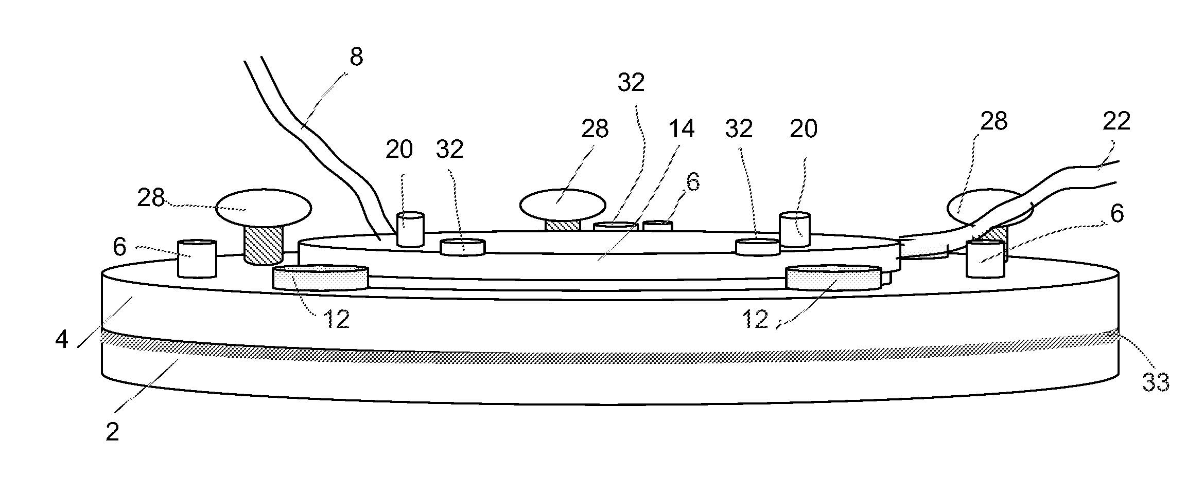
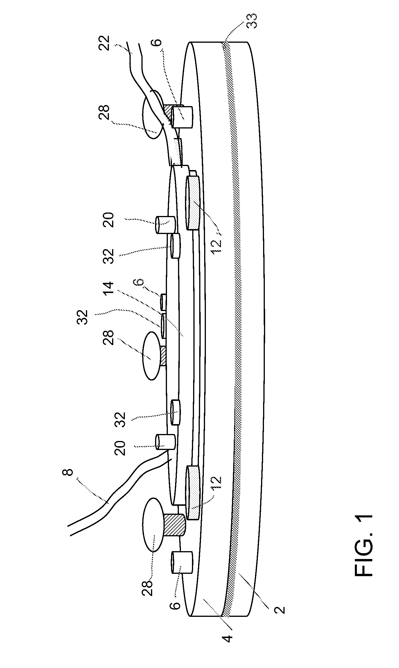
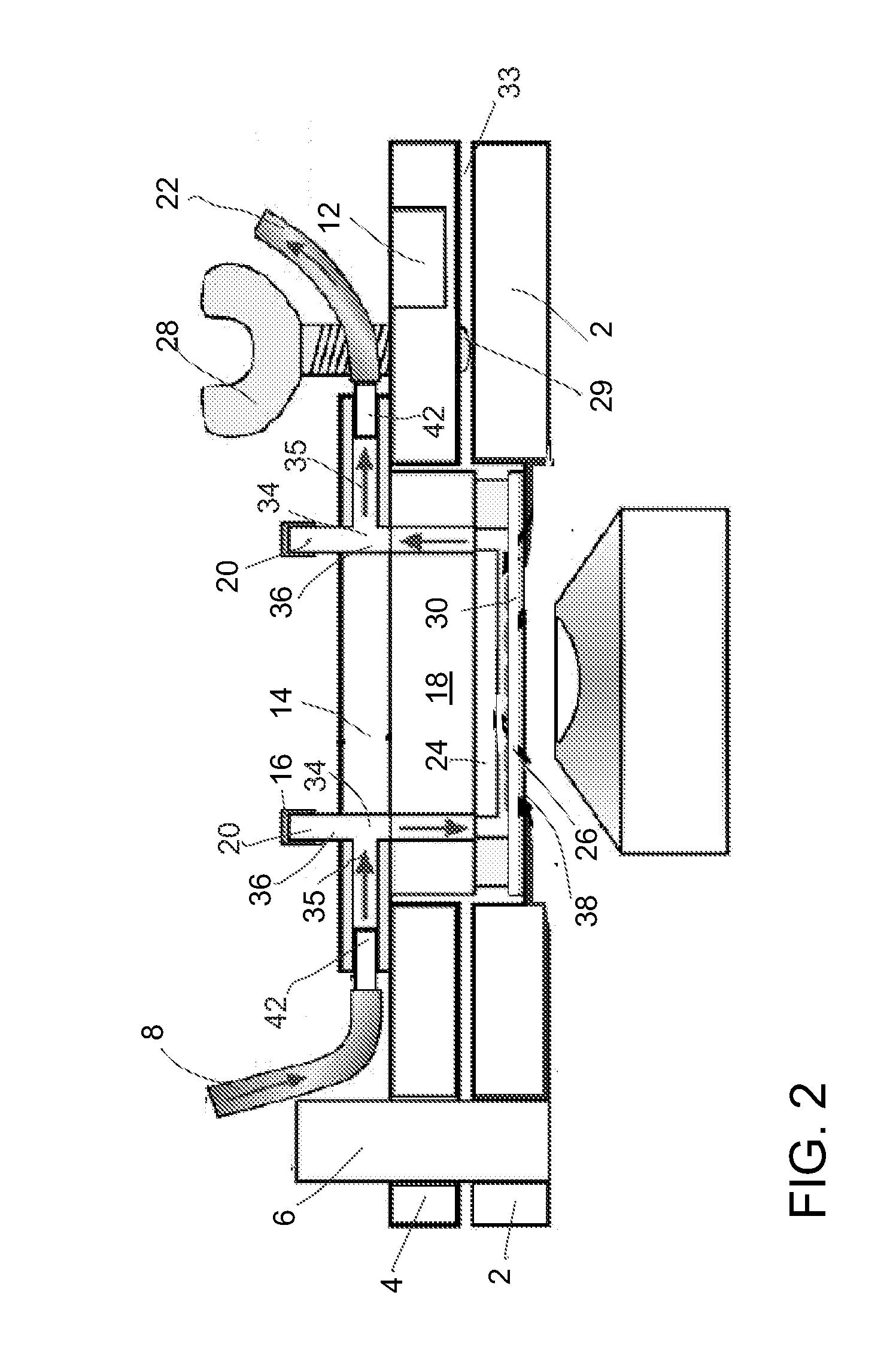
[0042]The microfluidic device used in this test had a microchannel network with 8 separate rectilinear test regions and with surface shear stress varying by a factor of ˜2 between each region, thus covering a 128-fold range in the shear stress, from low venous to arterial.

[0043]Human Umbilical Vein Endothelial Cells (HUVECs) (Cambrex) were grown in endothelial basal medium (EBM-2) containing endothelial growth factor supplements (EGM-2 bullet kit, Cambrex). Circular 25 mm, #2 cover glasses were rinsed in methanol, spin-dried, treated for 5 seconds with air plasma using a laboratory corona treater (BD-20AC, by Electro-Technic Products, Inc., IL), and coated with fibronectin by placing a droplet of a 5 μg / ml fibronectin solution onto a cover glass and incubating it for 1 hr. The cover glass surface was subsequently blocked by 30 min incubation under a 1% solution of heat-denatured BSA. An estimated 0.5×10⁶ HUVEC cells were plated on the fibronectin-coat...

example 2

Endothelial Cells Under Shear Flow

[0059]As a second test of the magnetic clamp and microfluidic chip, and to demonstrate their utility for live cell applications, a series of experiments were run with endothelial cells under shear flow, including experiments on the alignment of endothelial monolayer and healing of a scratch wound in it.

[0060]The endothelium monolayer and the microchannel network were examined immediately after the clamp was closed and the device was sealed. Consistently, there was no visible damage to the endothelium at the bottom of the microchannels, no clogging of the relatively narrow resistance channels by cells, and no detached cells in the microchannels. Cells near side walls of the test regions did not suffer any detectable damage (or viability problems) from possible motion of the chip in the plane of the cover glass (twist) during the setup closing. Moreover, many cells immediately adjacent to the walls, whose parts were cut by the PDMS chip, rapidly recov...

example 3

Transfection of Cells

[0063]To demonstrate the feasibility of transfection of cells in the monolayer using a standard protocol and of the subsequent visualization of fluorescently tagged cells under shear flow, a plasmid encoding fluorescent protein pmAKAR3 was used. This protein has two separate fluorescent domains, cyan and yellow (CFP and YFP), and a phosphorylation target specific to protein kinase A (PKA). The distance between the two fluorescent domains is reduced when the target is phosphorylated. Therefore, this protein can serve as a Förster resonance energy transfer (FRET) reporter of intracellular PKA activity. Transient transfections of endothelium monolayer were performed using FuGENE 6 transfection reagent (Roche Diagnostics) and a protocol provided by the manufacturer. A mixture of the plasmid and FuGENE 6 reagent diluted with a serum-free medium (100 μL) was directly pipetted onto a cover glass with a confluent endothelial monolayer. The fraction of cells that were tr...


PUM


Abstract

In a microfluidic system, a magnetic clamp for sealing a flexible microchannel chip includes a base formed from a magnetically-attractable material. The base supports a window for viewing the face of the microfluidic chip. A ring with magnets uniformly distributed around it is disposed over the base. A transparent disk attached to the top of the ring has an inlet and an outlet for introducing and removing a fluid medium into a cavity defined the disk, the window, the center opening of the ring and the base. An elastomer cushion is attached to the inner surface of the disk. The magnetic force between the base and the magnets on the ring compresses the cushion against the microfluidic chip so that the microchannels are sealed against the window with a uniform and reproducible pressure.

Description

RELATED APPLICATIONS[0001]This application claims the priority of U.S. Provisional Application No. 61 / 236,017, filed Aug. 21, 2009, which is incorporated herein by reference.GOVERNMENT RIGHTS[0002]This invention was made with government support under Grant No. NIRT 0608863 awarded by the National Science Foundation (NSF), and Grants No. HL078784 and No. AR27214 awarded by the National Institutes of Health (NIH). The government has certain rights in the invention.FIELD OF THE INVENTION[0003]The present invention relates to a device for reversibly sealing microfluidic chips against cover glasses and a method for using such a microfluidic system.BACKGROUND OF THE INVENTION[0004]Rolling and arrest of platelets on surfaces with various extracellular matrix (ECM) proteins under shear stress is central to hemostasis. Similarly, rolling and arrest of leukocytes (neutrophils and monocytes) on surfaces with various adhesion molecules plays an important role in inflammation and atherosclerosis...

Claims


Application Information

Patent Timeline
IPC IPC(8): B01L3/00B01L99/00
CPCB01L3/502715B01L9/527B01L2200/025C12M23/16B01L2300/0864B01L2300/123B01L2400/0478B01L2300/0816C12M41/36
Inventor GROISMAN, ALEXANDERGUTIERREZ, EDGARTKACHENKO, EUGENEGINSBERG, MARK H.
Owner RGT UNIV OF CALIFORNIA
Why Eureka
Try Eureka