Iron Oxyfluoride Electrodes for Electrochemical Energy Storage

a technology of iron oxyfluoride and electrochemical energy storage, which is applied in the direction of iron halides, non-metal conductors, cell components, etc., can solve the problems of large crystallographic distortion range, limiting the realization of such energy density increase, and little to prevent shearing

Active Publication Date: 2011-03-17
RUTGERS THE STATE UNIV
View PDF1 Cites 29 Cited by
  • Summary
  • Abstract
  • Description
  • Claims
  • Application Information

AI Technical Summary

Problems solved by technology

The main limiting factor to the realization of such energy density increase is the positive electrode materials.
The transition metals present in all of the intercalation compounds are capable of multiple electron transfer and thus higher capacity, however, the limited lithium vacancies inhibit the incorporation of more lithium and thus the charge transfer of more electrons to the structure.
There is little to prevent shearing of these crystal structures hence there is a large range of crystallographic distortions upon moving from the ReO3 structure to the PdF3 structure.
Although such materials have been isolated before, none have been examined as possible electrode materials for lithium batteries.
2000) previously reported the solid state synthesis of FeOxF2-x solid-solutions utilizing FeF2 and FeOF precursors, a significant disadvantage of this fabrication technique is that it requires the preliminary synthesis of FeOF, which cannot be formed below 925° C. Moreover, synthesis of the FeOxF2-x solid-solutions was performed under controlled atmosphere and very high temperatures (850° C. for 3 hours) that resulted in the formation of macrocrystalline compounds.

Method used


Image

  • Iron Oxyfluoride Electrodes for Electrochemical Energy Storage
  • Iron Oxyfluoride Electrodes for Electrochemical Energy Storage
  • Iron Oxyfluoride Electrodes for Electrochemical Energy Storage

Examples


example 1.1

Solution Fabrication Process Methodology

[0105]Nanostructured iron (oxy)fluoride materials of tunable oxygen content were fabricated through a solution fabrication process from iron metal and fluorosilicic acid (H2SiF6) aqueous solutions. Briefly, iron metal (10 grams) in powder form was dissolved in 141 grams of a 20-25 wt % fluorosilicic acid in water solution. The mixture was placed at 40-45° C. overnight to allow the reaction of the metal with the fluorosilicic acid. After filtering the excess iron metal, the resulting green solution was placed in air at 110° C. until a dry powder formed. An alternative route consisted in drying the solution for 2-3 hours at 200° C. (e.g., on a stirring hotplate) prior to drying at 110° C. The latter process reduced the processing time considerably. Both routes resulted in the synthesis of a FeSiF6 hydrate compound in the powder form.

[0106]FIG. 30 shows an illustrative x-ray diffraction (XRD) pattern for the rhombohedral R-3m FeSiF6.6H2O compound...

example 1.2

Effect of Annealing Temperature, Time and Atmosphere on the Iron (Oxy)Fluoride Composition: X-Ray Diffraction

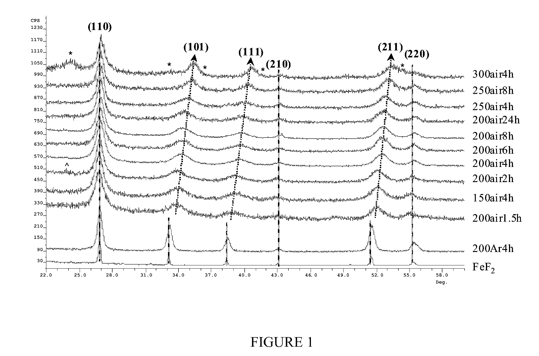
[0109]The solution fabrication process described herein was utilized to synthesize FeF2 compound. This FeF2 compound was distinct from commercially obtained FeF2. When synthesized under argon (Ar), the synthesized FeF2 compound showed no evidence of any second phase while the FeF2 obtained from the commercial source contained small amounts of a Fe2F5.2H2O hydrate. Further, the broader diffraction peaks associated with the compound obtained by the solution fabrication process indicates that crystallite size (22 nm) of the newly fabricated material was one order of magnitude smaller than the commercial source (>100 nm) (FIG. 1). The crystallite size was determined with the Scherrer formula using the (110) diffraction peaks.

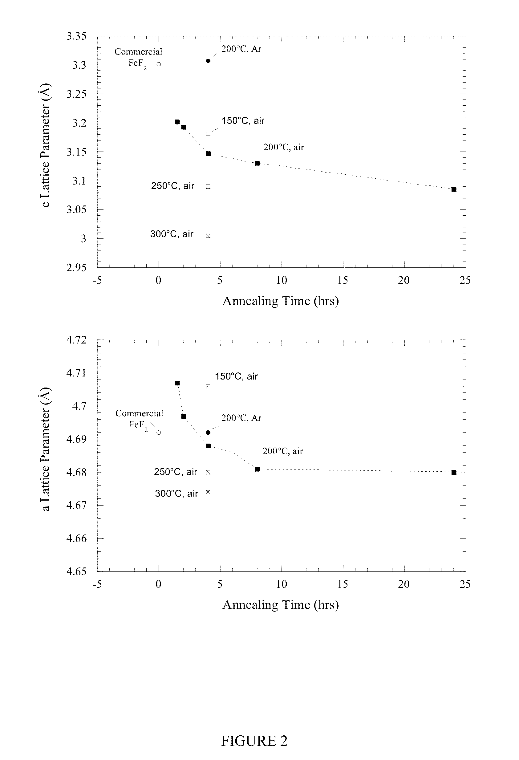
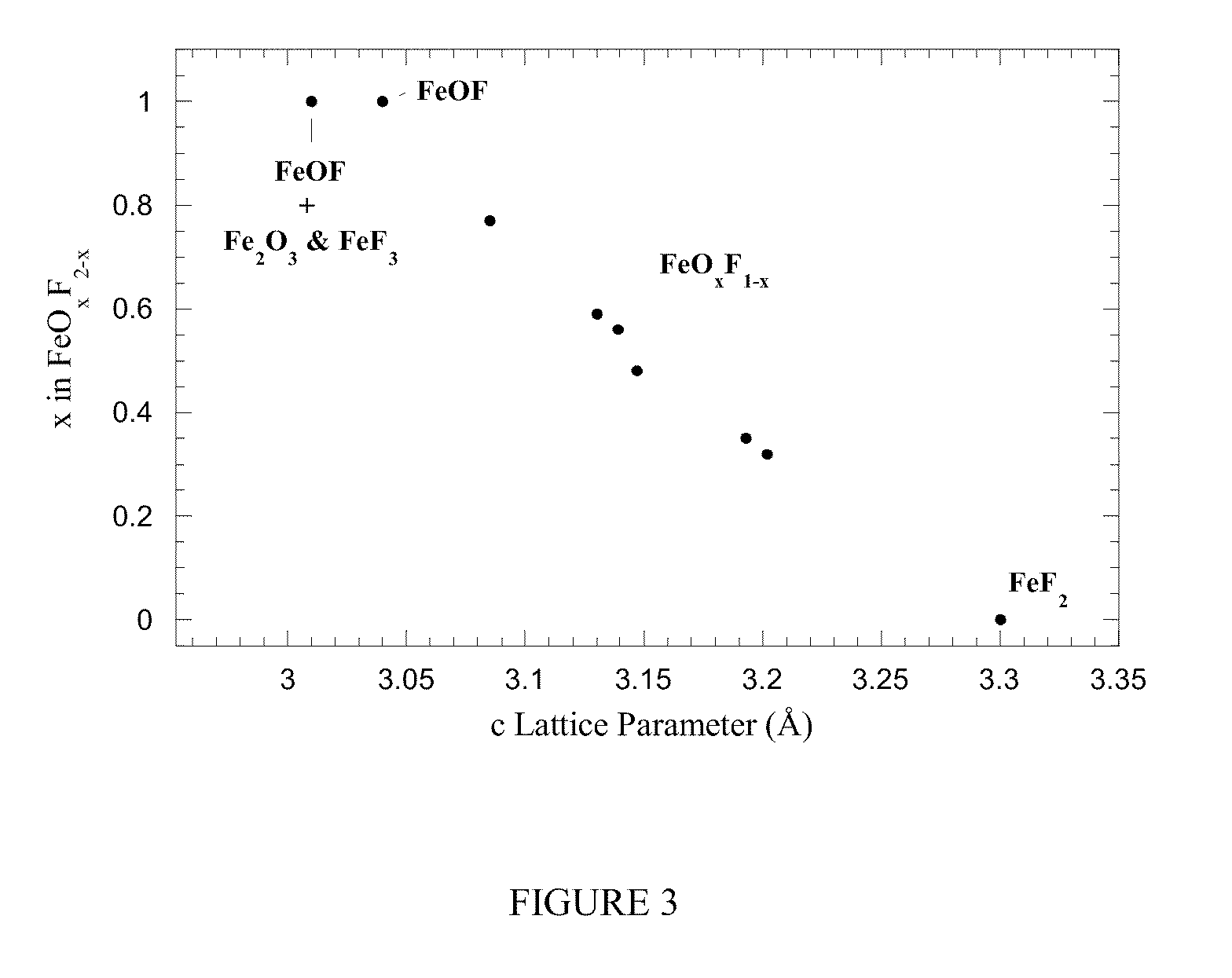
[0110]Upon annealing in air at temperatures as low as 150° C., the FeSiF6 hydrate converts into a rutile-type tetragonal material of P42 / mnm space group simi...

example 2

Carbon-Iron (oxy)fluoride Nanocomposites

Example 2.1

Synthesis of Carbon-FeF2 Nanocomposites

[0112]Carbon-iron fluoride nanocomposites were fabricated by mechanical milling of activated carbon with (i) solution fabrication process derived FeF2, or (ii) commercial FeF2. The milling vessel was loaded and sealed either in a helium (He)-filled glove box or in a dry room with 2 / mnm system symmetry as demonstrated by XRD, shown in FIG. 4. However, milling induced a slight change in the lattice parameters correlated to the splitting of the (220) and (002) Bragg peaks in the 55° 2θ region. This phenomenon was more pronounced with the solution fabrication process derived FeF2, where the splitting stems from a small increase of the a-lattice parameter, which is concomitant with a small decrease of the c-lattice parameter (Table 2).

TABLE 2Unita latticec latticeCrystalliteBETCell Vol.parameterparameterSizeS.A.Samples(Å3)(Å)(Å)(nm)(m2 / g)Commercial FeF272.614.690 ± .0023.300 ± .004>1001.4Solution-ba...


PUM

PropertyMeasurementUnit
domain sizeaaaaaaaaaa
temperatureaaaaaaaaaa

Abstract

The present invention provides electrochemical energy storage systems comprising metallolyte composites, iron fluoride composites and iron oxyfluoride composites. The present invention further provides methods for fabricating metallolyte composites.

Description

CROSS REFERENCE TO RELATED APPLICATIONS[0001]This application claims the benefit of priority to U.S. Provisional Application No. 61 / 055,791, filed May 23, 2008, the entire contents of which are incorporated herein by reference.STATEMENT OF GOVERNMENT FUNDING[0002]This invention was made with U.S. government support. The government has certain rights in the invention.FIELD OF THE INVENTION[0003]The present invention relates to primary and secondary electrochemical energy storage systems, particularly to such systems as battery cells, which use materials that take up and release ions as a means of storing and supplying electrical energy.BACKGROUND OF THE INVENTION[0004]Lithium rechargeable batteries are the premier energy storage device for portable electronics applications. However, a significant need remains for the improvement of the energy density of the cells. The main limiting factor to the realization of such energy density increase is the positive electrode materials.[0005]All...

Claims


Application Information

Patent Timeline
Patent Type & Authority Applications(United States)
IPC IPC(8): H01M4/54H01M4/50H01M4/52H01M4/56H01M4/58H01M4/88H01B1/06H01B1/02
CPCC01G49/00C01G49/02C01G49/10C01P2002/52C01P2002/72H01M4/625C01P2006/40H01M4/523H01M4/582H01M4/5825H01M4/624C01P2002/77Y02E60/10
Inventor PEREIRA, NATHALIEAMATUCCI, GLENN
Owner RUTGERS THE STATE UNIV
Why Eureka
Try Eureka