
Bioabsorbable Stent With Time Dependent Structure And Properties And Regio-Selective Degradation

Inactive Publication Date: 2011-03-17
ABBOTT CARDIOVASCULAR
View PDF29 Cites 57 Cited by
  • Summary
  • Abstract
  • Description
  • Claims
  • Application Information

AI Technical Summary

Benefits of technology

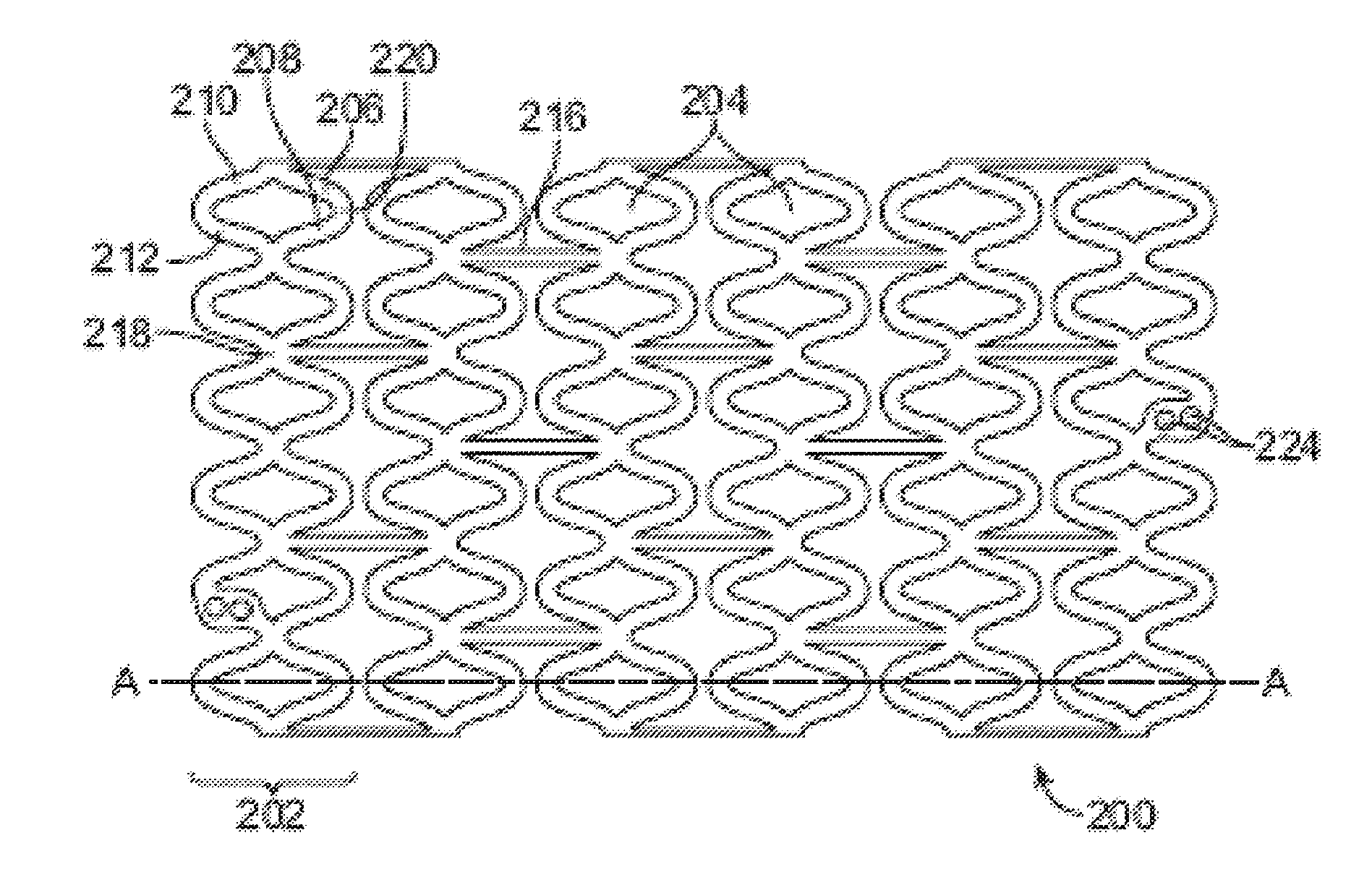
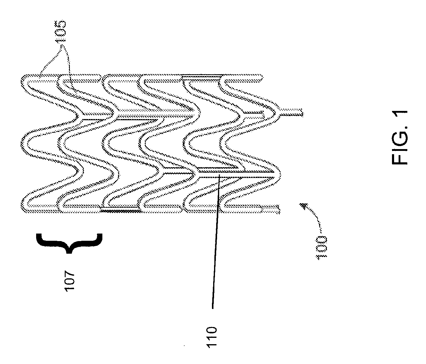
[0013]Various embodiments of the present invention include a stent for treating a diseased section of a blood vessel, comprising: a bioabsorbable polymeric scaffolding composed of a pattern of struts, the pattern including a plurality of cylindrical rings connected by linking struts, wherein each of the linking struts between at least one set of adjacent rings comprises a coating material above at least a portion of the linking struts that is different from the ring struts, and wherein the coating material accelerates degradation of the linking struts and causes the linking struts to break before the rings of the scaffolding when the stent is deployed in a living body.
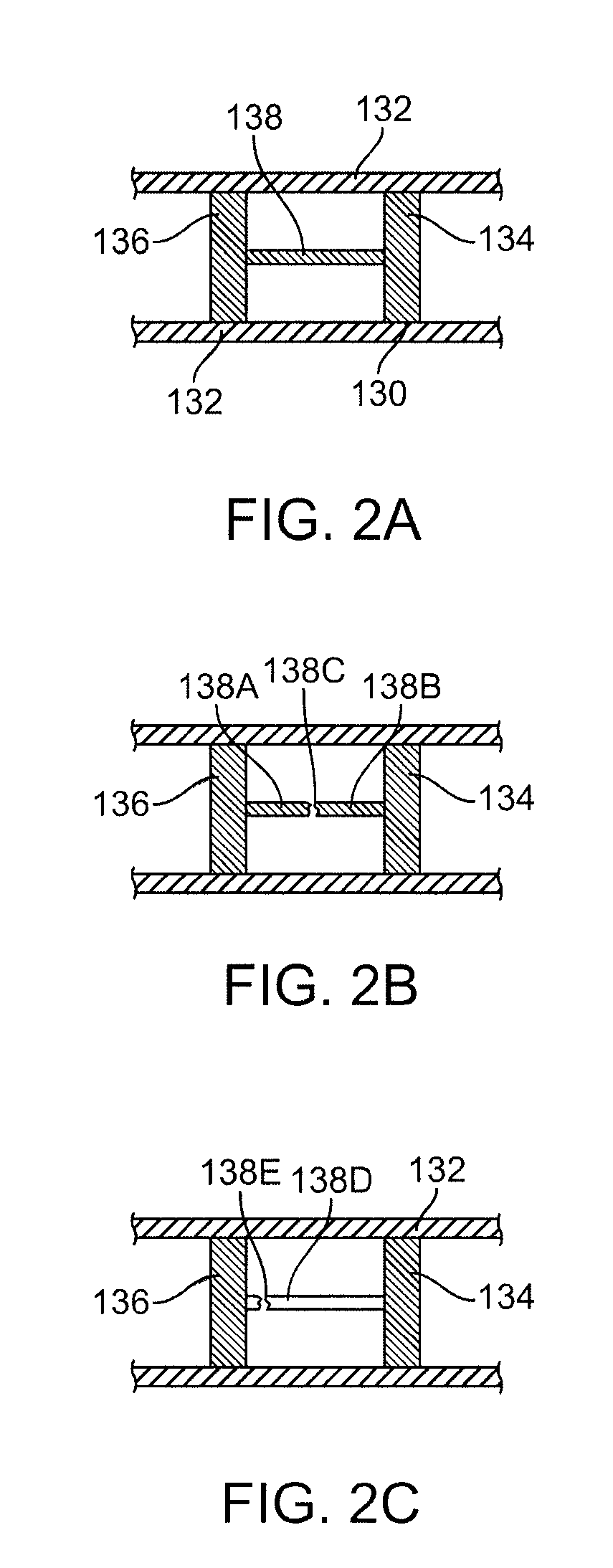
[0015]Further embodiments of the present invention include a method of making a stent, comprising: providing a bioabsorbable polymeric scaffolding composed of a pattern of struts, the pattern including a plurality of cylindrical rings connected by linking struts; and applying a coating selectively to a region of at least one of the linking struts between at least one set of adjacent rings, wherein the coating induces chemical degradation of the scaffolding polymer in the region which lowers the Mw or Mn of the scaffolding polymer in the region, and wherein the lower Mw or Mn reduces the tensile strength, strain to failure, and fracture resistance of the region that causes the one or more linking struts to break prematurely as compared to the remainder of the scaffolding when the stent is deployed in a living body.
[0016]Other embodiments of the present invention include a method of making a stent, comprising: providing a bioabsorbable polymeric scaffolding composed of a pattern of struts, the pattern including a plurality of cylindrical rings connected by linking struts; and selectively modifying a region of at least one of the linking struts between at least one set of adjacent rings, wherein the modification is selected from the group consisting of exposure to radiation in the IR to UV wavelength, exposure to e-beam radiation, exposure to gamma radiation, exposure to neutron bombardment, exposure to reactive ion etching, exposure to plasma, direct heating, and exposure to ultrasound frequency application, wherein the modification induces chemical degradation of the scaffolding polymer in the region which lowers the Mw or Mn of the scaffolding polymer in the region, and wherein the lower Mw or Mn reduces the tensile strength, strain to failure, and fracture resistance of the region that causes the one or more linking struts to break prematurely as compared to the remainder of the scaffolding when the stent is deployed in a living body.

Problems solved by technology

Yet, restenosis remains a significant problem.
When restenosis does occur in the stented segment, its treatment can be challenging, as clinical options are more limited than for those lesions that were treated solely with a balloon.
Effective concentrations at the treated site require systemic drug administration which often produces adverse or even toxic side effects.
For a variety of reasons, the performance of stents in the SFA appear to be more problematic than in coronary vessels and in other peripheral vascular beds, such as the iliac and carotid arteries.
This may be due to the significant mechanical stresses placed on the devices in the dynamic SFA environment relative to other vasculature, as well as the vessel length and the severity of stenotic and occlusive disease.
However, a stent made out of such biostable material tends to retain mechanical or structural integrity and remains at the implant site indefinitely unless it is removed by intervention or is dislodged.
Intervention presents risks to the patient and dislodgement can have significant adverse consequences on the patient.
One disadvantage is that the stented segment has the compliance of the stent which is very different from that of healthy vessel segment.
Another drawback of such durably implanted stents is that the permanent interaction between the stent and surrounding tissue can pose a risk of endothelial dysfunction and late thrombosis.

Method used


Image

  • Bioabsorbable Stent With Time Dependent Structure And Properties And Regio-Selective Degradation
  • Bioabsorbable Stent With Time Dependent Structure And Properties And Regio-Selective Degradation
  • Bioabsorbable Stent With Time Dependent Structure And Properties And Regio-Selective Degradation

Examples


Embodiment Construction

[0032]Coronary arteries refer generally to arteries that branch off the aorta to supply the heart muscle with oxygenated blood. Peripheral arteries refer generally to blood vessels outside the heart and brain.

[0033]In both coronary artery disease and peripheral artery disease, the arteries become hardened and narrowed or stenotic and restrict blood flow. In the case of the coronary arteries, blood flow is restricted to the heart, while in the peripheral arteries blood flow is restricted leading to the kidneys, stomach, arms, legs and feet. The narrowing is caused by the buildup of cholesterol and other material, called plaque, on their inner walls of the vessel. Such narrowed or stenotic portions are often referred to as lesions. Artery disease also includes the reoccurrence of stenosis or restenosis that occurs after an angioplasty treatment. Although there are probably several mechanisms that lead to restenosis of arteries, an important one is the inflammatory response, which indu...


PUM

PropertyMeasurementUnit
Timeaaaaaaaaaa
Lengthaaaaaaaaaa
Thicknessaaaaaaaaaa

Abstract

A bioabsorbable polymeric stent with time dependent structure and properties and methods of treating a diseased blood vessel with the bioabsorable polymeric stent are disclosed. The structure and properties of the stent change with time and allow the vessel to be restored to a natural unstented state. The bioabsorbable stent loses mechanical integrity in a controlled manner due to modification of selected structural elements.

Description

BACKGROUND OF THE INVENTION[0001]1. Field of the Invention[0002]This invention relates to methods of treatment of blood vessels with bioabsorbable polymeric medical devices, in particular, stents.[0003]2. Description of the State of the Art[0004]This invention relates to radially expandable endoprostheses, that are adapted to be implanted in a bodily lumen. An “endoprosthesis” corresponds to an artificial device that is placed inside the body. A “lumen” refers to a cavity of a tubular organ such as a blood vessel. A stent is an example of such an endoprosthesis. Stents are generally cylindrically shaped devices that function to hold open and sometimes expand a segment of a blood vessel or other anatomical lumen such as urinary tracts and bile ducts. Stents are often used in the treatment of atherosclerotic stenosis in blood vessels. “Stenosis” refers to a narrowing or constriction of a bodily passage or orifice. In such treatments, stents reinforce body vessels and prevent restenosi...

Claims


Application Information

Patent Timeline
IPC IPC(8): A61F2/82B05D3/00
CPCA61F2/91A61F2/915A61L31/06A61L31/10A61F2230/0054A61L31/148A61F2/89C08L67/04A61F2210/0004A61F2250/0036A61F2002/828
Inventor TROLLSAS, MIKAELDAVALIAN, DARIUSHNGO, MICHAEL HUYHSIAO, HAO-MINGANUKHIN, BORISHOSSAINY, SYED F.A.GALE, DAVID C.
Owner ABBOTT CARDIOVASCULAR
Learn More