
Organic light-emitting material, organic light-emitting element using the same and method of forming the same

Inactive Publication Date: 2011-07-07
LUMINESCENCE TECH
View PDF7 Cites 8 Cited by
  • Summary
  • Abstract
  • Description
  • Claims
  • Application Information

AI Technical Summary

Benefits of technology

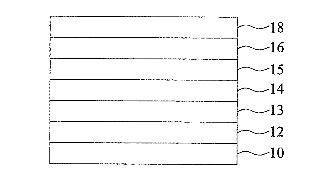
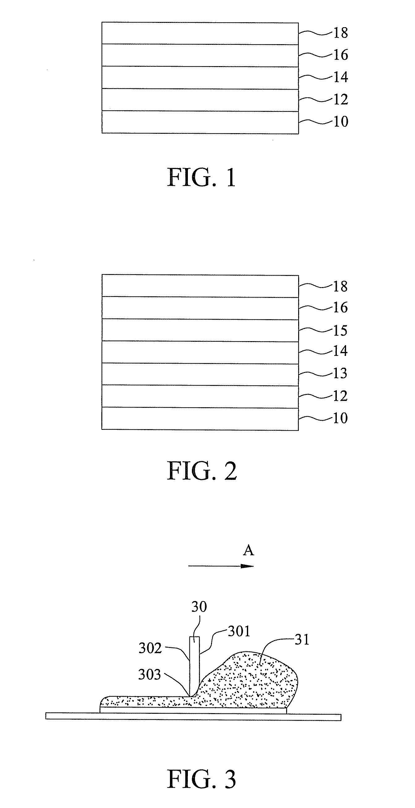
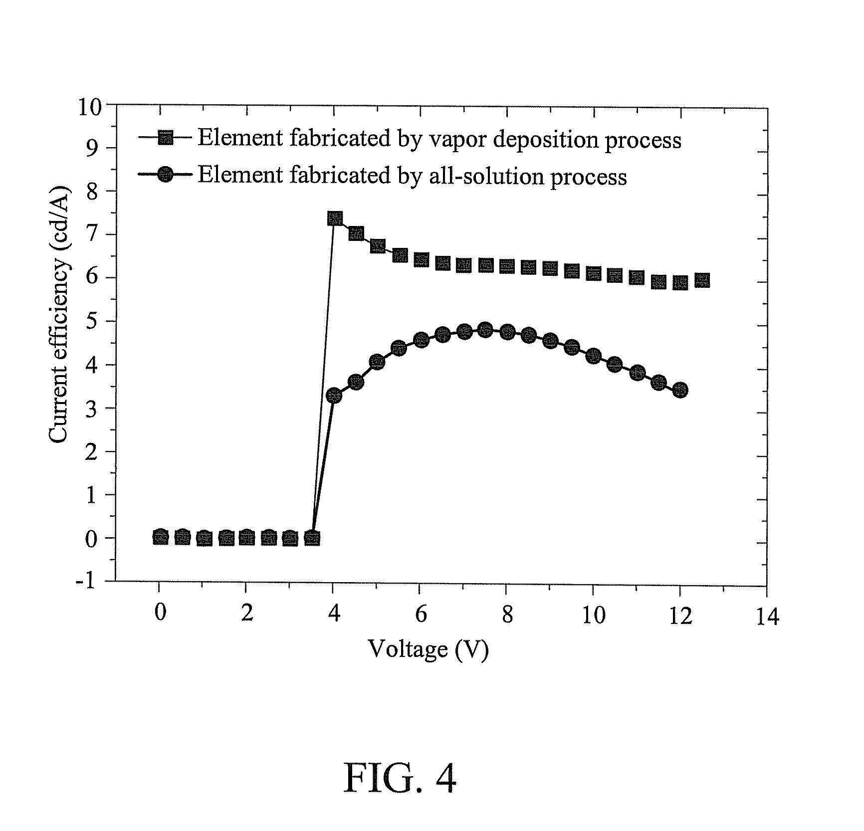
[0008]The small molecular compounds of the present invention are used as organic light-emitting materials. When the compounds are coupled with the scraper coating technique, an organic light-emitting element having a multi-layered structure is obtained without miscibility among the layers in an all-solution state. As such, the film is formed by small molecules. Further, the method of the present invention forms an element or device having a large surface area and lower production cost.

Problems solved by technology

However, in the process, a highly vacuum chamber is required to perform thermal vapor deposition, and material usage efficiency is low.
Thus, the cost of the vapor deposition process is very high.
Further, the vapor deposition process has slow processing rate due to the complexity of the operation, and is not suitable for fabricating an element or device having a large surface area.
Nevertheless, due to the miscibility among layers as caused by the solution process, the macromolecular OLEDs are generally mono-layered, such that the products cannot meet the industrial demands.
However, such prior art does not have general applicability since it uses cross-linked molecules as the first organic layer to avoid dissolution, so as to overcome the miscibility among layers.
The publication on Applied Physics Letters, 92, 063302 (2008) discloses adding small molecules for an electron transport layer and a light-emitting layer, but the efficiency and performance of the OLED are poor.
Moreover, the publication on Applied Physics Letters, 92, 093307 (2008) discloses using an adhesive method, which does not provide a good control of the thickness and filming characteristics of each layer.
Although the above methods have been developed for improving a solution process, there still exist many drawbacks.

Method used


Image

  • Organic light-emitting material, organic light-emitting element using the same and method of forming the same
  • Organic light-emitting material, organic light-emitting element using the same and method of forming the same
  • Organic light-emitting material, organic light-emitting element using the same and method of forming the same

Examples


synthesis example 1

SYNTHESIS OF A REPRESENTATIVE COMPOUND OF FORMULA (I)

Step 1

[0039]100 ml of toluene and 50 ml of ethanol were added to a 250 ml three-necked flask. Deaeration was performed for 30 minutes by adding nitrogen gas. In the presence of nitrogen gas, 4.9 g of pyrene-1-boronic acid (20 mmol), 12.1 g of 7-dibromo-di-n-octylfluorene (22 mmol), 0.2 g of tetrakis triphenyl palladium (Pd(PPh3)4) and 50 ml of 2 M sodium carbonate (Na2CO3) solution were added thereto, and stirred overnight while the temperature reached 60° C. to obtain a reaction solution. The reaction solution was filtered, and then extracted with water and toluene. The obtained organic layer was dewatered, evaporated under a reduced pressure, and then purified by using a silica gel column to give 7.8 g of a product, 2-bromo-7-pyrenyl-9,9-di-n-octylfluorene (yield: 58%), which had a structure of the following formula.

Step 2

[0040]A 100 ml three-necked flask was dewatered. In the presence of nitrogen, 50 ml of dewatered tetrahydrof...

synthesis example 2

SYNTHESIS OF A REPRESENTATIVE COMPOUND OF FORMULA (II)

Step 1

[0046]A 500 ml round-bottomed flask was dewatered, and then 20 ml of dimethyl formamide (DMF) was added thereto. In an ice bath, 15.3 g of phosphorus oxychloride (POCl3) (0.1 mmol) was added dropwisely, and stirred for 10 minutes at a temperature ranging from 5 to 10° C. after the addition was completed. An amount of 38 g of N-phenyl-N,N-di(4-n-hexylphenyl)aniline (91 mmol) was dissolved in 200 ml of DMF to obtain a mixture. The mixture was added slowly and dropwisely into the flask. After the addition was completed, heating was performed at a temperature ranging from 60 to 70° C., and a reaction took place overnight to obtain a reaction solution. The reaction solution was slowly poured into 1 L of water, neutralized to a reach neutral pH by using 20 wt % of a sodium hydroxide solution, and extracted with ethyl acetate. The obtained organic layer was concentrated under a reduced pressure, and then purified by using a silica...

synthesis example 3

SYNTHESIS OF A REPRESENTATIVE COMPOUND Of FORMULA (a)

Step 1

[0051]100 ml of toluene and 50 ml of ethanol were added to a 250 ml three-necked flask. Deaeration was performed for 30 minutes by adding nitrogen gas. In the presence of nitrogen gas, 4.9 g of pyrene-l-boronic acid (20 mmol), 12.1 g of 7-dibromo-di-n-octylfluorene (22 mmol), 0.2 g of tetrakis triphenyl palladium (Pd(PPh3)4) and 50 ml of 2M sodium carbonate (Na2CO3) solution were added thereto, and stirred overnight while the temperature reached 60° C. to obtain a reaction solution. The reaction solution was filtered, and then extracted with water and toluene. The obtained organic layer was dewatered, evaporated under a reduced pressure, and then purified by using a silica gel column to give 7.8 g of a product, 2-bromo-7-pyrenyl-9,9-n-octylfluorene (yield: 58%), which had the structure of the following formula.

Step 2

[0052]A 100 ml three-necked flask was dewatered. In the presence of nitrogen, 50 ml of dewatered tetrahydrofur...


PUM

PropertyMeasurementUnit
Volumeaaaaaaaaaa
Weightaaaaaaaaaa
Surface areaaaaaaaaaaa

Abstract

The present invention provides compound of formula (I)wherein each substituent is defined in the specification. The compound may be used, in combination with other organic light-emitting materials, in a light-emitting layer of an organic light-emitting element. The present invention also provides an organic light-emitting element including a first electrode, a second electrode and at least three layers of organic material layers disposed between the first electrode and the second electrode, wherein the layer used as a light-emitting layer contains a compound of formula (I). Further, an all-solution process, which is used for fabricating the organic light-emitting element of the present invention, has the advantages such as avoiding miscibility among the layers to fabricate an element with a large surface area and lower production cost.

Description

FIELD OF INVENTION[0001]The present invention relates to organic light-emitting materials, and more particularly, to an organic light-emitting material for a light-emitting layer of an organic light-emitting element, an organic light-emitting element using the same and a method of forming the same.BACKGROUND OF THE INVENTION[0002]In the developments of organic conductors, insulators and semiconductor materials, organic semiconductor materials, such as organic light-emitting devices (OLED), organic light emitting diodes (LED), solar cells, organic transistors and organic photodetectors, are important for the electronic and photoelectronic elements. Generally, OLEDs are classified into small molecular OLEDs and macromolecular OLEDs. A small molecular dye or pigment is a host material in a small molecular OLED, whereas a conjugative macromolecule is a host material in a macromolecular OLED. Currently, a vapor deposition process is performed on typical small molecular light-emitting dio...

Claims


Application Information

Patent Timeline
IPC IPC(8): H01L51/54H01L51/52H01L51/56C07C13/66C07C211/54
CPCC07C13/66C07C211/54C07C211/61C07C2103/18C07C2103/24C07C2103/50H01L51/0007H01L51/0054H01L51/0058H01L51/0059H01L51/006H01L51/5012H01L51/0003C07C2603/18C07C2603/24C07C2603/50H10K71/12H10K85/622H10K85/631H10K85/626H10K85/633H10K50/11H10K71/15
Inventor MENG, HSIN-FEIHORNG, SHENG-FUTSENG, HSIN-RONGYU, CHIA-DAYEH, CHUNG-LINHUANG, SHENG-YANGYEN, FENG-WENLIN, I-FENG
Owner LUMINESCENCE TECH
Learn More