Wavelength Division Multiplexing Transmission Equipment

Active Publication Date: 2011-09-08
HUAWEI TECH CO LTD
View PDF19 Cites 9 Cited by
  • Summary
  • Abstract
  • Description
  • Claims
  • Application Information

AI Technical Summary

Benefits of technology

[0014]In the proposed new scheme the laser previously used for transmitting data from the client equipment card to the line interface card is replaced by an optical modulator device. Continuous wave light from a shared multi-wavelength source is coupled to the modulator through a wavelength selective filter. The filter selects one wavelength from the many wavelengths generated by the multi-wavelength source. By choosing suitable filters each modulator can operate at a different wavelength. The outputs from all the modulators located on one or more client equipment cards can then be multiplexed together onto one or more fibres before optical amplification and onward transmission. The use of modulators rather than fixed wavelength lasers located on the client cards reduces the need for the network operator to hold a large inventory of different wavelength specific client cards and avoids the costs associated with the alternative of tunable lasers. For networks where it is necessary to reassign wavelengths to particular client cards during operation a modification to the proposed scheme is possible by the incorporation of an optical switch.
[0015]A preferred optical modulator for use in the present invention is one that is able to modulate optical pulses at bit rates greater than 2.5 gbit/s, preferably up to at least 10 Gbit/s, more preferably up to 40 Gbit/s, and provide output optic

Problems solved by technology

However, because the cost of operating a core network is shared amongst a wide number of people, the core network can normally afford to have larger numbers of high specification devices than smaller networks to ensure the reliability of the core network.
Conversely, access networks are smaller in reach and number of users and therefore network architectures and the devices used to implement access networks are typically chosen with cost in mind.
It is desirable in access networks to choose devices with operating specifications that are suitable for accomplishing the task they are assigned to do but which do not have performances that are over and above the performance which is required of them as such high performance devices are unnecessarily expensive and reduce the cost effectiveness of the network.
For a DWDM system a critical issue is the ability to control the wavelength of the transmitter lasers so they remain within the wavelength grid specified by the international standards bodies.
However, a tunable laser still adds significantly to the cost of the client equipment and requires additional control and management systems to be associated with the client card.
To provide the necessary control of the laser wavelength it is usually necessary to temperature control the laser which significantly increases the electrical power consumed by the client card.
RSOAs that are electrically modulated produce pulses with high degrees of chirp that

Method used


Image

  • Wavelength Division Multiplexing Transmission Equipment
  • Wavelength Division Multiplexing Transmission Equipment
  • Wavelength Division Multiplexing Transmission Equipment

Examples


first embodiment

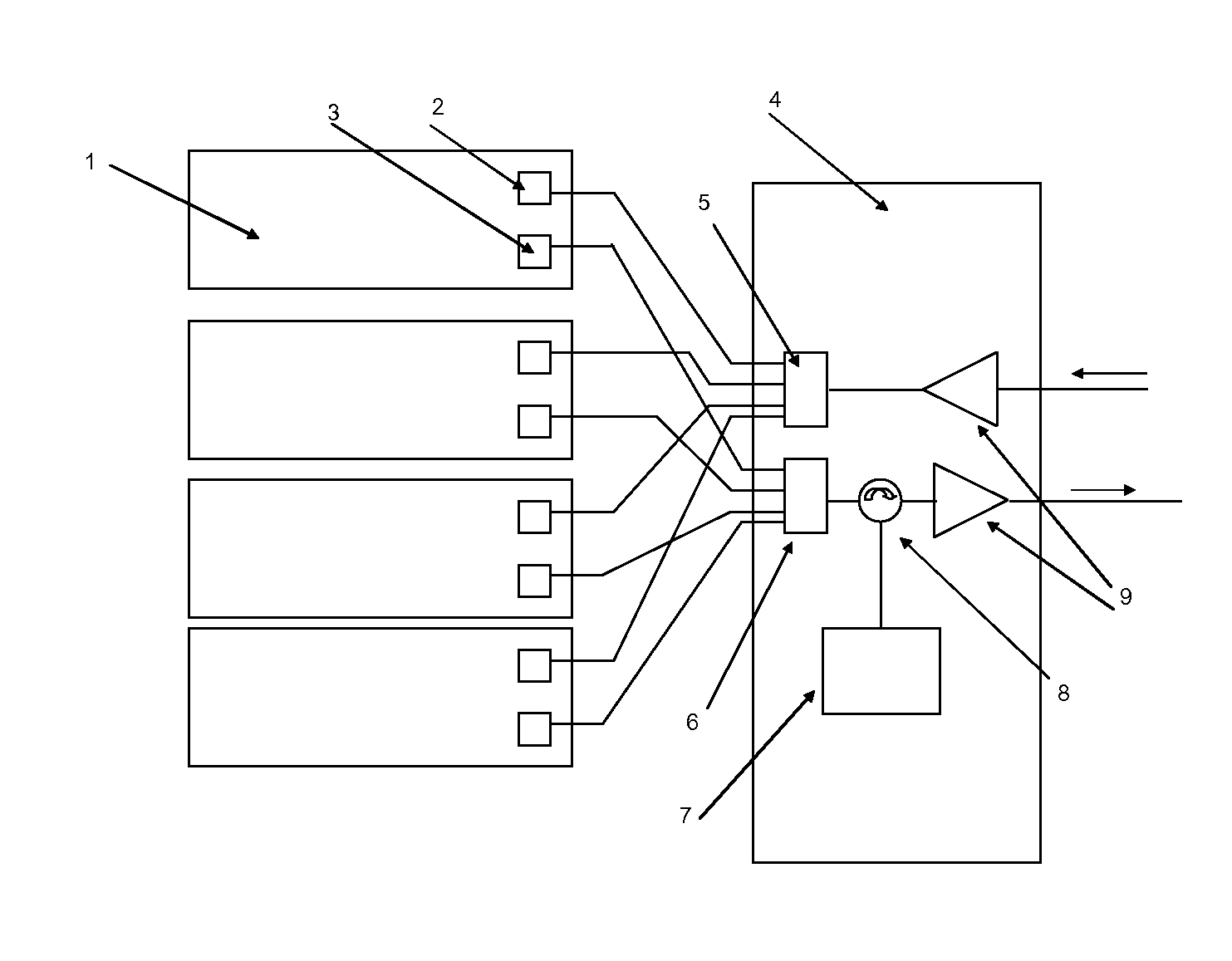
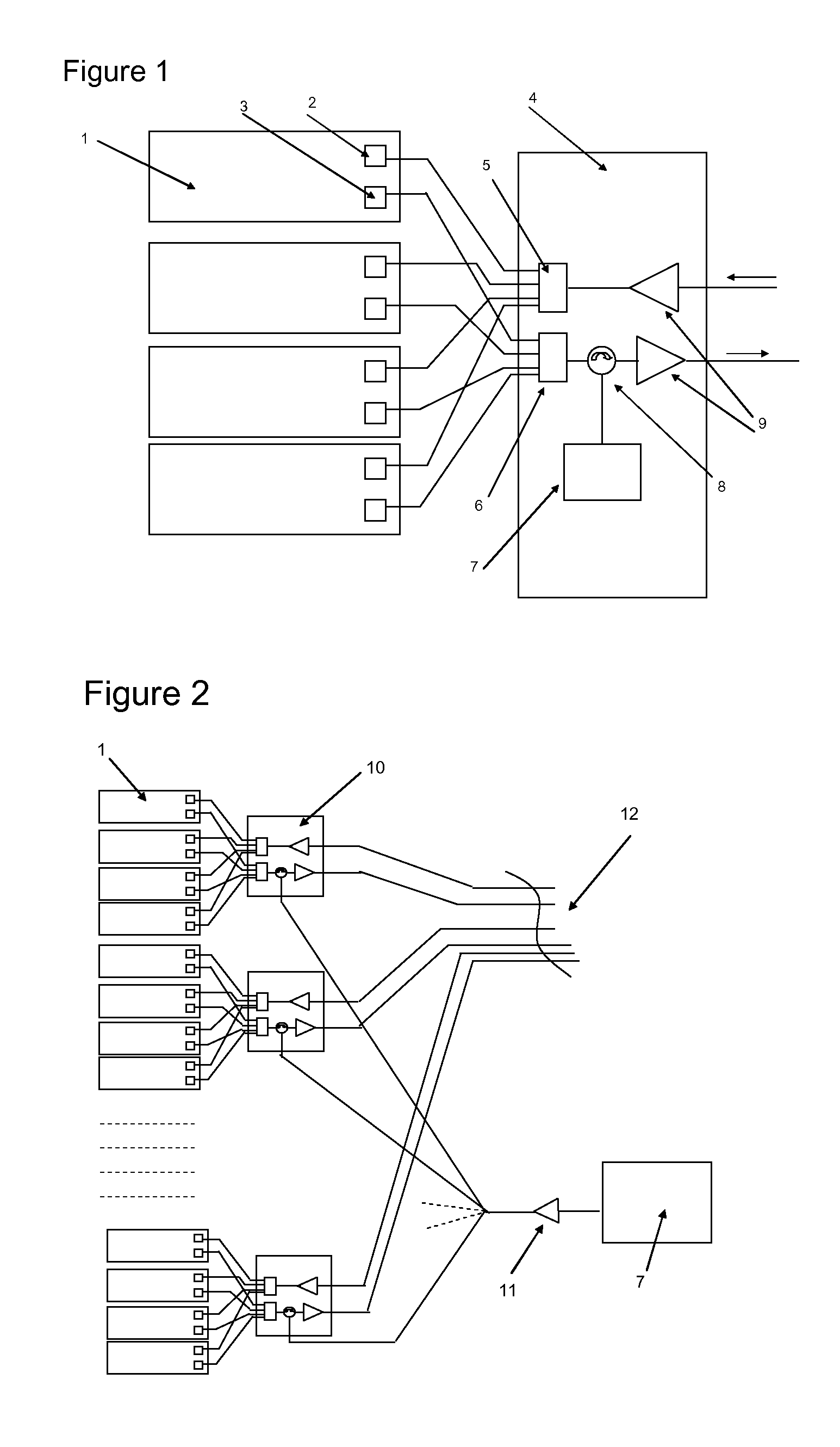
[0066]A first embodiment is illustrated in FIG. 1. Light from a centralised multi-wavelength source 7 producing M (typically 32) wavelengths is combined using a wavelength multiplexer to provide a single fibre output. The multi-wavelength source 7 is typically a hybrid integrated laser module containing M single wavelength lasers combined together using a planar array waveguide multiplexer. A suitable configuration for a multi-wavelength a source 7 with attractive features for this application is described in patent publication EP2082464 (A1) “Multi-wavelength Transmitter”. The combined output from the multi-wavelength source 7 is connected via a circulator 8 to an AWG 6 which acts as both a wavelength multiplexer and de-multiplexer of light coming from and to optical modulators 3. Connections from the opposite side of the AWG 6 are connected to the optical modulators 3 located on individual client equipment cards 1. The modulators 3 would typically be reflective electro-absorption ...

second embodiment

[0068]the present invention is shown in FIG. 2. In this arrangement a multi-wavelength source 7 is shared between several of the transmission systems which were described in the previous embodiment. Each of the transmission systems in this embodiment comprises a line card10 and a plurality of client cards 1. The multiple wavelength source 7 is located externally of the line cards 10. To overcome the losses resulting from sharing the multi-wavelength source 7 with multiple line cards 10, an optical amplifier 11 is included in this scheme and is connected between the source 7 and the point where the optical connection from the source 7 splits to connect to the different line cards 10. Typically this amplifier 11 would be an erbium doped fibre amplifier but other designs could also be used, including either a semiconductor optical amplifier or Raman amplifier.

third embodiment

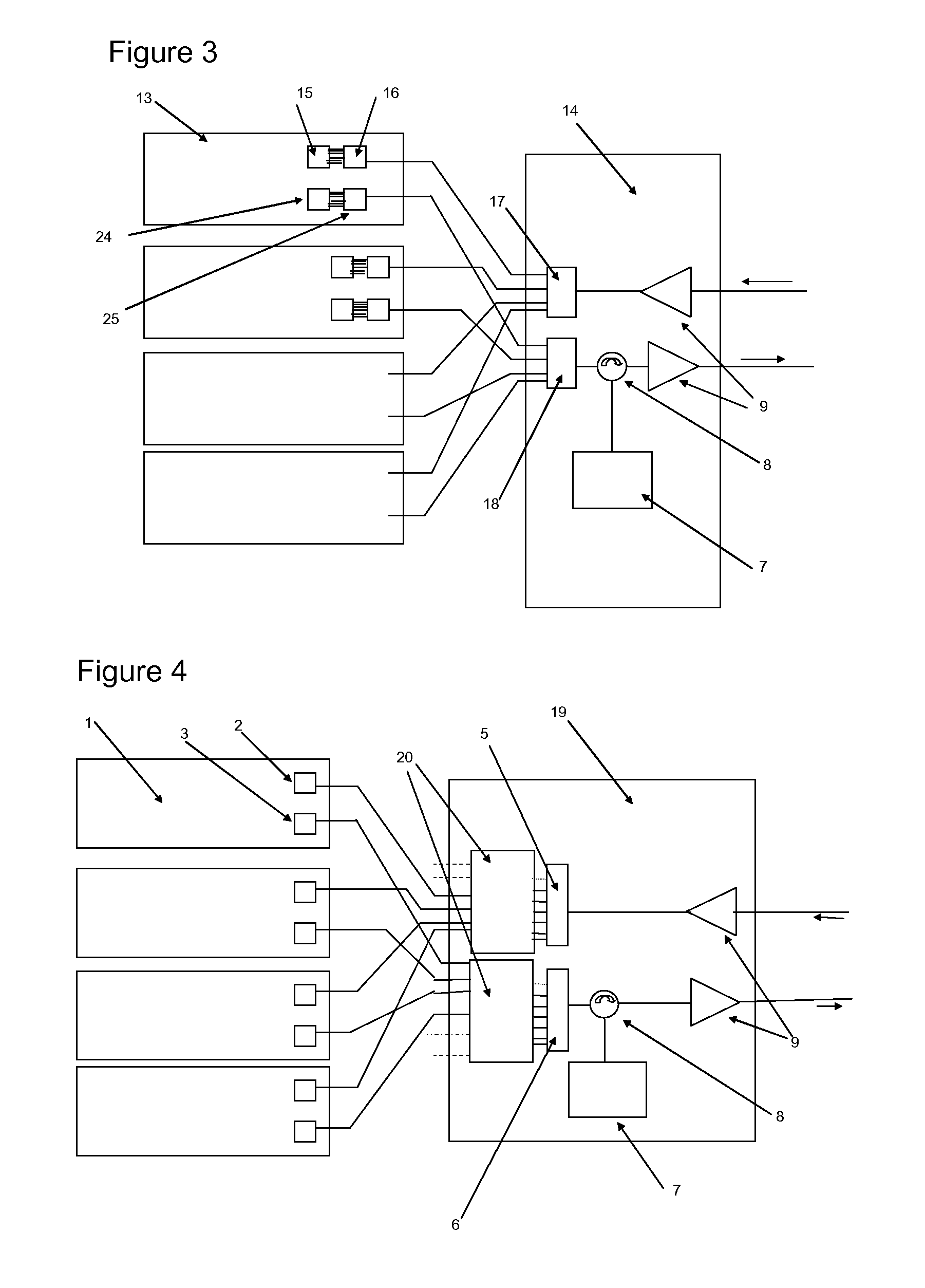
[0069]A third embodiment is shown in FIG. 3. In this arrangement multiple wavelengths are fed to each client equipment card 1. On each client equipment card a wavelength de-multiplexer 25 (third wavelength routing element), typically an AWG device, is used to separate individual wavelengths from a plurality of wavelengths generated by a multi-wavelength source 7. An array 24 consisting of a plurality of reflective modulators on the client card 13 is used to impose data generated by the client equipment onto a set of wavelengths. The output from the array 24 of reflective modulators is then recombined using the same AWG device 25. In the example shown in FIG. 3, each client card 13 produces 10 channels each channel spaced by an optical frequency of 200 GHz. The channels on each client card 13 are multiplexed using an AWG with a flat top profile. The outputs from several client cards are then further multiplexed using an inter-leaver 18 (first wavelength routing element) on a line sid...


PUM


Abstract

An optical transmission network comprises a multi-wavelength source (7) shared between multiple sets of client side equipment for manipulating electrical signals. A first wavelength selective routing element (5) is connected to the multi-wavelength source (7). Each set of client-side equipment (1) comprises an optical modulator (3) connected to the first wavelength selective routing element (5) and an optical receiver (2). A second wavelength selective routing element (6) is connected to the optical receiver (2) and is operative to direct incoming signals from one or more remote locations to the optical receiver (2). The network provides a WDM architecture solution for networks whereby the cost of implementing and running client side equipment (1) is reduced by not having the WDM source (7) within the client side equipment (1).

Description

FIELD OF INVENTION[0001]This invention relates to telecommunication and computer networks. In particular the present invention is concerned with optical communication networks operating at data rates of 2.5 Gbit / s or greater.RELATED ART[0002]Optical communications from one location to another typically get transmitted over a number of different networks. Each type of network typically has different operating requirements and equipment depending on the distance the network has to transmit data, the number of different destinations that the network provides for and the budgetary constraints of running the network. The central part of a network is often called the core network. A core network is typically designed to be able to connect to and provide interconnection for a number of smaller ‘access networks’ and other smaller networks geographically located apart from each other by large distances, for example over 100 km, or 1000 km. A core network needs to be able to handle large amou...

Claims


Application Information

Patent Timeline
IPC IPC(8): H04J14/02
CPCH04J14/02
Inventor SMITH, DAVID WILLIAM
Owner HUAWEI TECH CO LTD
Why Eureka
Try Eureka