Production process for lithium-silicate-system compound

a lithium-silicate system and lithium-silicate technology, applied in the direction of non-metal conductors, cell components, sustainable manufacturing/processing, etc., can solve the problems of low capacity, low environmental load, and inability to withstand charging voltage, etc., to achieve low environmental load, reduce the effect of oxygen elimination and high capacity

Active Publication Date: 2011-12-01
NAT INST OF ADVANCED IND SCI & TECH +1
View PDF5 Cites 21 Cited by
  • Summary
  • Abstract
  • Description
  • Claims
  • Application Information

AI Technical Summary

Benefits of technology

[0174]The lithium-silicate-system compounds that are obtainable by means of the processes according to the present invention are inexpensive, are those which are obtainable using raw materials that are abundant in the resource amounts and are low in the environmental loads, and are materials that can keep down the elimination of oxygen in a case where they are used as a positive-electrode active material for lithium-ion secondary battery.
[0175]In particular, in accordance with the present invention, it is possible to obtain lithium-silicate compounds, which are useful as positive-electrode active materials for lithium-i

Problems solved by technology

However, these compounds have such a problematic issue that the oxygen is likely to be eliminated before and after 150° C. under the fully-charged conditions so that this is likely to cause the oxidative exothermic reactions of nonaqueous electrolyte liquids.
However, in a positive-electrode material comprising an olivine-type phosphate compounds, its theoretical capacity is limited to 170 mAh/g approximately because of the large molecular weight of phosphate polyanions.
Furthermore, LiCoPO4 and LiNiPO4 have such a problem that no electrolytic liquids, which can withstand their charging voltages, are available because the operating voltages are too high.
Of these methods, although it is feasible to obtain fine particles with particle diameters of from 1 to 10 nm approximately by means of the hydrothermal synthesis method, there is such a problem that doping elements are less likely to dissolve and so the phases of impurities are like

Method used


Image

  • Production process for lithium-silicate-system compound
  • Production process for lithium-silicate-system compound
  • Production process for lithium-silicate-system compound

Examples


example no.1

Example No. 1

Lithium-Rich Silicate-System Compound, and Charging-Discharging Characteristics of Battery Using the Same

[0183]

[0184]0.03 mol of iron oxalate, FeC2O4.2H2O (produced by SIGMA-ALDRICH, and with 99.99% purity), and 0.03 mol of lithium silicate, Li2SiO3 (produced by KISHIDA KAGAKU, and with 99.5% purity), were used as raw materials; and these were mixed with a carbonate mixture (e.g., one which was made by mixing lithium carbonate (produced by KISHIDA KAGAKU, and with 99.9% purity), sodium carbonate (produced by KISHIDA KAGAKU, and with 99.5% purity) and potassium carbonate (produced by KISHIDA KAGAKU, and with 99.5% purity) in a ratio of 0.435:0.315:0.25 by mol). The mixing proportion was set at such a proportion that a summed amount of the iron oxalate and lithium silicate was 225 parts by weight with respect to 100 parts by weight of the carbonate mixture. After adding 20 mL of acetone to these, they were mixed by a ball mill made of zirconia at a rate of 500 rpm for 60 ...

example no.2

Example No. 2

Manganese-Containing Lithium-Silicate-System Compound

[0201]A powder of manganese-containing lithium-silicate-system compound was obtained under the same conditions as those of Example No. 1, using manganese oxalate instead of the iron oxalate used in Example No. 1.

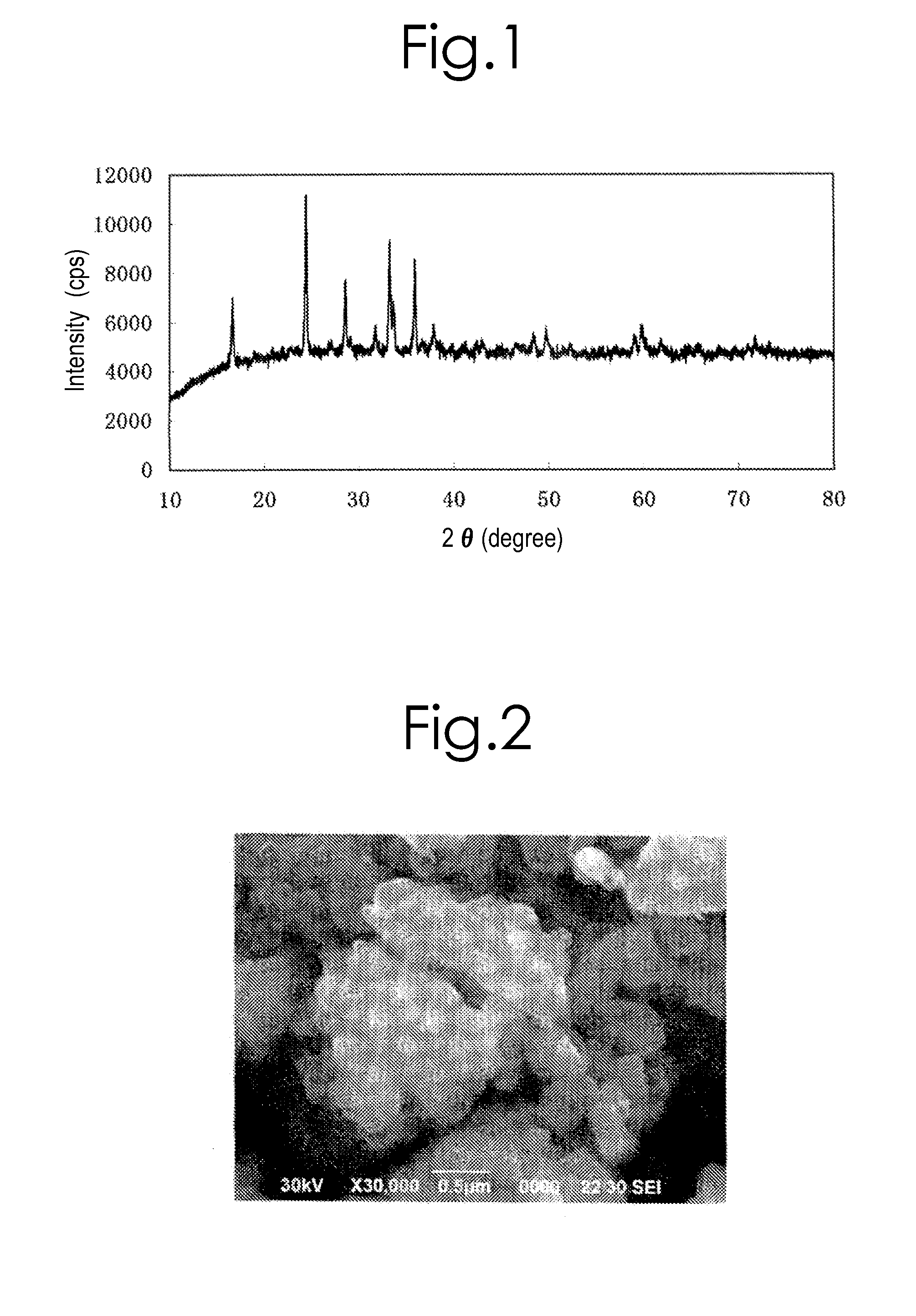
[0202]An X-ray diffraction measurement was carried out for the obtained product by means of a powder X-ray diffraction apparatus with use of the CuKα ray. The XRD pattern of this product agreed with the XRD pattern of orthorhombic crystal in the space group “Pmn21” virtually.

[0203]Moreover, it was possible to ascertain that the product was a powder that comprised crystal particles with about 200 nm or less by means of a scanning electron microscope (or SEM) observation. In addition, as a result of doing elemental analysis for the aforesaid product by means of an inductively-coupled plasma (or ICP) method, it was possible to ascertain that it came to have a compositional formula, Li1.980Na0.016K0.025Mn1.062SiO4...

example no.3

Example No. 3

[0212]Lithium-rich silicate-system compounds, which were expressed by a compositional formula: Li2+a+bAbM1-xM′xSiO4+c (in the formula, “A” is at least one element that is selected from the group consisting of Na, K, Rb and Cs; “M” is at least one element that is selected from the group consisting of Fe and Mn; “M′” is at least one element that is selected from the group consisting of Mg, Ca, Co, Al, Ni, Nb, Ti, Cr, Cu, Zn, Zr, V, Mo and W; and the respective subscripts are specified as follows: 0≦x≦0.5; 0

[0213]Note that, as for the raw materials, the following were used: iron oxalate, FeC2O4.2H2O (produced by SIGMA-ALDRICH, and with 99.99% purity); lithium silicate, Li2SiO3 (produce...


PUM


Abstract

The present invention is one which provides a production process for lithium-silicate-system compound, the production process being characterized in that: a lithium-silicate compound being expressed by Li2SiO3 is reacted with a substance including at least one member of transition-metal elements that is selected from the group consisting of iron and manganese at 400-650° C. in a molten salt of a carbonate mixture comprising lithium carbonate and at least one member of alkali-metal carbonates that is selected from the group consisting of potassium carbonate, sodium carbonate, rubidium carbonate and cesium carbonate in a mixed-gas atmosphere including carbon dioxide and a reducing gas; and a positive-electrode active material for lithium-ion secondary battery that comprises a lithium-silicate-system compound being obtained by the aforesaid process.
In accordance with the present invention, it becomes feasible to produce lithium-silicate-system materials, which are useful as positive-electrode active materials for lithium-ion secondary battery, and the like, by means of relatively simple and easy means.

Description

TECHNICAL FIELD[0001]The present invention relates to a production process for lithium-silicate-system compound, which is useful as the positive-electrode active materials of lithium-ion batteries, and the like, and to uses or applications for the lithium-silicate-system compound that is obtainable by this process.BACKGROUND ART[0002]Lithium secondary batteries have been used widely as power sources for portable electronic instruments, because they are small-sized and have high energy densities. As for their positive-electrode active materials, lamellar compounds, such as LiCoO2, have been employed mainly. However, these compounds have such a problematic issue that the oxygen is likely to be eliminated before and after 150° C. under the fully-charged conditions so that this is likely to cause the oxidative exothermic reactions of nonaqueous electrolyte liquids.[0003]Recently, as for positive-electrode active material, olivine-type phosphate compounds, Li″M″PO4 (LiMnPO4, LiFePO4, LiC...

Claims


Application Information

Patent Timeline
IPC IPC(8): H01M4/58H01B1/18
CPCC01B33/32Y02E60/122H01M10/052H01M4/5825Y02E60/10C01B33/12H01M4/58Y02P70/50
Inventor KOJIMA, TOSHIKATSUSAKAI, TETSUOMIYUKI, TAKUHIROOKUMURA, YASUEKOJIMA, AKIRANIWA, JUNICHIMURASE, HITOTOSHI
Owner NAT INST OF ADVANCED IND SCI & TECH
Why Eureka
Try Eureka