Increased Stability of a Complex Material Stack in a Semiconductor Device by Providing Fluorine Enriched Interfaces

a technology of complex materials and interfaces, applied in semiconductor devices, semiconductor/solid-state device details, electrical apparatus, etc., can solve the problems of increasing production yield, increasing the amount of dielectric materials, and achieving very complex integrated circuits executing sophisticated tasks, so as to achieve superior adhesion and thus chemical stability, and efficiently applied

Inactive Publication Date: 2012-02-02
GLOBALFOUNDRIES US INC
View PDF5 Cites 4 Cited by
  • Summary
  • Abstract
  • Description
  • Claims
  • Application Information

AI Technical Summary

Benefits of technology

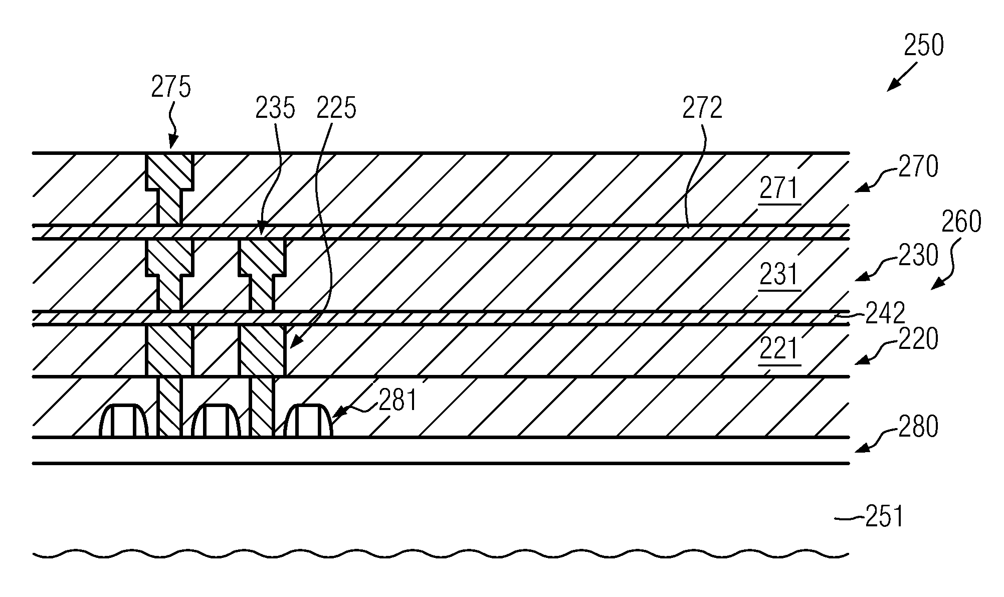
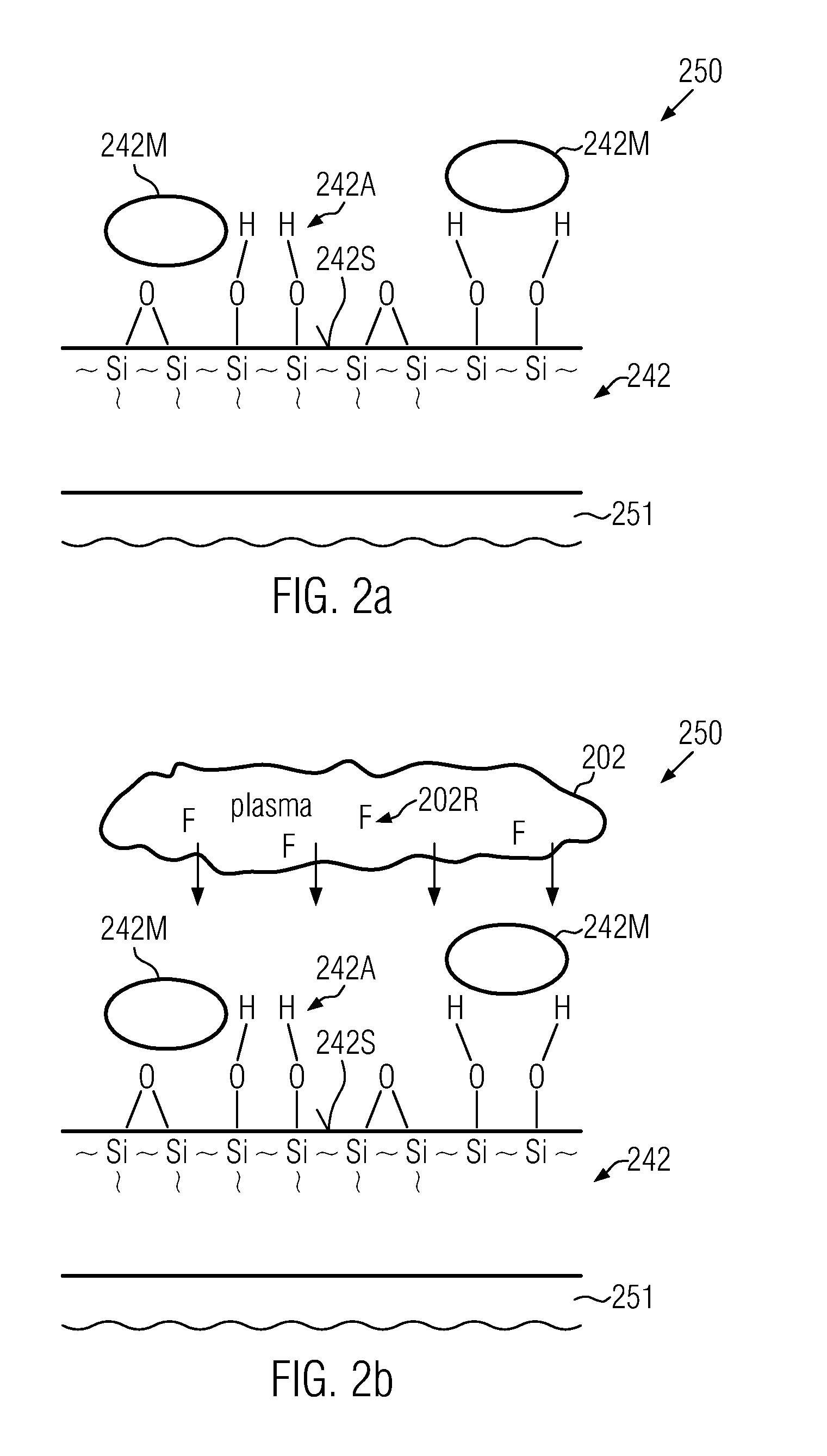
[0019]Generally, the present disclosure provides semiconductor devices and manufacturing techniques in which the interface characteristics between a silicon-containing dielectric material and a subsequent material layer may be significantly improved by establishing modified surface conditions prior to the actual deposition of the subsequent material layer. To this end, a surface treatment on the basis of fluorine radicals may be applied in order to form silicon / fluorine bonds at the surface of the silicon-containing material layer prior to actually forming the subsequent material layer on the basis of a chemical deposition process. The fluorine radicals may be provided in the form of a “gentle” surface treatment, i.e., without causing significant surface damage, which may be accomplished by appropriately controlling the concentration of fluorine radicals in the reactive process ambient. In this manner, chemical bonds at the surface of the silicon-containing material layer formed between silicon and other atomic species or molecules may be efficiently replaced by chemical bonds between the silicon and the fluorine, thereby resulting in a removal of any unwanted atomic species or molecules. Furthermore, due to the surface modification caused by the fluorine radicals, even any other molecules adhering to the surface may be efficiently removed, thereby also creating a significant cleaning effect prior to actually depositing a further material layer. Upon performing a chemical deposition process, i.e., any deposition process in which a chemical bond may be established between surface atoms or molecules and any component provided in a deposition ambient, for instance in chemical vapor deposition (CVD) processes and any related deposition techniques, such as atomic layer deposition (ALD) and the like, the silicon / fluorine bond may be broken up and the fluorine may be replaced by the chemically active component in the deposition ambient. In this manner, chemical bonds may be established most efficiently between the silicon atoms of the underlying material layer and the chemically active components of the deposition ambient, while the fluorine species may react with other components, such as carbon and the like, depending on the specific deposition conditions.
[0020]Consequently, in sophisticated semiconductor devices, dielectric material layers which may be comprised of silicon, at least at a surface thereof, may be efficiently used as deposition surfaces for forming thereon any further materials on the basis of a high fraction of chemical bonds, thereby providing superior adhesion and thus chemical stability. In some illustrative embodiments disclosed herein, the concept of a surface treatment based on fluorine radicals may be efficiently applied to the dielectric materials of sophisticated metallization systems so that even ULK materials, or any other sensitive low-k dielectric materials, may be efficiently provided on a silicon-containing dielectric material without requiring any additional material layers or graded material compositions, thereby reducing the amount of any dielectric materials having an increased dielectric constant.

Problems solved by technology

Thus, economic constraints drive semiconductor manufacturers to steadily increase the substrate dimensions, thereby also increasing the area available for producing actual semiconductor devices and thus increasing production yield.
Additionally, the size of the individual die regions on the wafer is increased in order to integrate more and more circuit portions, even of very different type, thereby achieving very complex integrated circuits executing sophisticated tasks.
For extremely scaled integrated circuits, the signal propagation delay is no longer limited by the circuit elements, such as field effect transistors and the like, but is limited, owing to the increased density of circuit elements requiring an even more increased number of electrical connections, by the close proximity of the metal lines, since the line-to-line capacitance is increased, while the conductivity of the lines is reduced due to a reduced cross-sectional area.
The density and mechanical stability or strength of the low-k materials, however, may be significantly less compared to the well-approved dielectrics silicon dioxide and silicon nitride.
Due to the reduced mechanical stability of advanced dielectric materials having a dielectric constant of 3.0 and less, device reliability may be affected by the provision of these materials during operation of sophisticated semiconductor devices and in particular during the further processing of the device caused by the interaction between a chip and the package due to a thermal mismatch of the corresponding thermal expansion of the different materials.
The introduction of ULK dielectric materials or porous dielectric materials into the metallization system of sophisticated semiconductor devices, however, may be associated with a further reduction of the mechanical stability of the complex metallization systems, which may thus require a precise balance between electrical performance and mechanical strength of the metallization system.
Furthermore, due to advances in process tool technology and the like, and due to the demand for providing semiconductor chips having incorporated therein more and more functional circuit portions, the die size has been increased, thereby requiring very complex metallization systems in which a significant portion of the dielectric material may be provided in the form of ULK or porous dielectric materials.
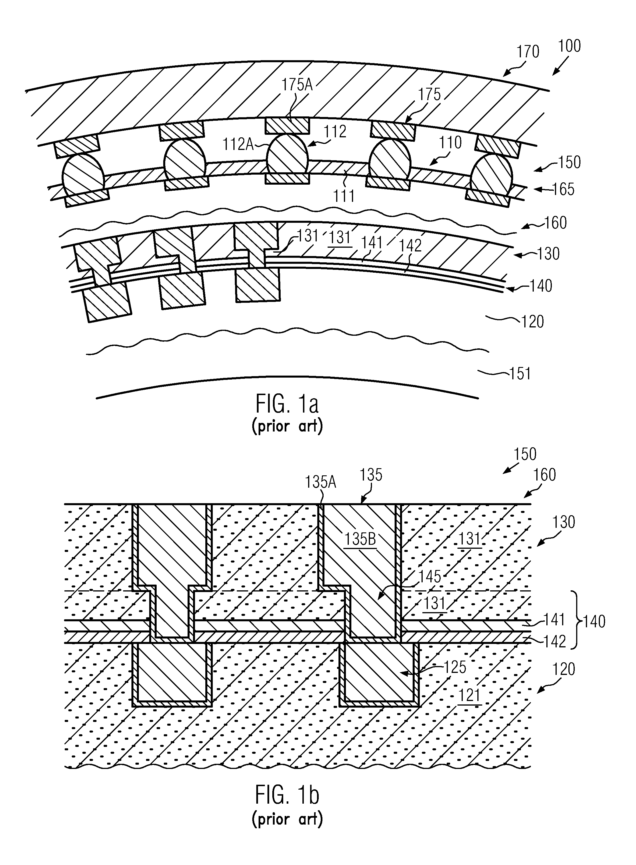
Consequently, the resulting temperature gradients induce mechanical shear forces during the reflow process, which may not be efficiently compensated for or buffered by the metallization system 160.
In particular, any interfaces between the various materials have been identified as a major source of device failures in the form of material delamination.
Although these various surface treatments may result in a somewhat superior adhesion of the ULK material, it turns out, however, that in particular for complex semiconductor devices requiring low dielectric constant values in combination with a plurality of stacked metallization layers in combination with a contact regime, as described above, possibly based on a lead-free solder material which may per se result in increased mechanical stresses due to the higher melting point and the increased stiffness of the lead-free solder material, nevertheless, significant yield losses and reduced reliability may be observed.
In other approaches, a concept may be applied in which the amount of ULK material may be reduced by providing materials of superior mechanical stability, as is for instance illustrated in the form of the layer 142, which, however, nevertheless may not resolve the problem of mechanically weak interfaces between any material layer and an overlying ULK material.
For these reasons, so-called transition layers or graded layers may be introduced in which the material composition may be appropriately varied so as to provide a substantially graded transition from one material composition to the material composition of the ULK material, which, however, may also result in the incorporation of a significant amount of dielectric material having an undesired high dielectric constant, while at the same time additional process complexity may also be required for the deposition of appropriate transition layers.

Method used


Image

  • Increased Stability of a Complex Material Stack in a Semiconductor Device by Providing Fluorine Enriched Interfaces
  • Increased Stability of a Complex Material Stack in a Semiconductor Device by Providing Fluorine Enriched Interfaces
  • Increased Stability of a Complex Material Stack in a Semiconductor Device by Providing Fluorine Enriched Interfaces

Examples


Embodiment Construction

[0035]Various illustrative embodiments of the invention are described below. In the interest of clarity, not all features of an actual implementation are described in this specification. It will of course be appreciated that in the development of any such actual embodiment, numerous implementation-specific decisions must be made to achieve the developers' specific goals, such as compliance with system-related and business-related constraints, which will vary from one implementation to another. Moreover, it will be appreciated that such a development effort might be complex and time-consuming, but would nevertheless be a routine undertaking for those of ordinary skill in the art having the benefit of this disclosure.

[0036]The present subject matter will now be described with reference to the attached figures. Various structures, systems and devices are schematically depicted in the drawings for purposes of explanation only and so as to not obscure the present disclosure with details ...


PUM

PropertyMeasurementUnit
dielectric constantaaaaaaaaaa
widthaaaaaaaaaa
dielectric constantaaaaaaaaaa

Abstract

When forming complex metallization systems, a sensitive material, such as a ULK material, may be deposited on a silicon-containing dielectric material, such as an etch stop material, with superior adhesion by performing a surface treatment on the basis of fluorine radicals. Due to the fluorine treatment, silicon-fluorine bonds are generated, which are then broken up upon interacting with the chemically active component during the further deposition process. Consequently, the subsequent material layer is chemically bonded to the underlying material, thereby imparting superior stability to the interface, which in turn may result in superior robustness and reliability of the metallization system upon performing reflowing processes and operating complex packaged semiconductor devices.

Description

BACKGROUND OF THE INVENTION[0001]1. Field of the Invention[0002]Generally, the present disclosure relates to integrated circuits, and, more particularly, to techniques for increasing mechanical stability of complex material stacks, for instance for reducing chip-package interactions caused by thermal mismatch between the chip and the package, in particular during reflowing a bump structure for directly connecting the chip and the package.[0003]2. Description of the Related Art[0004]Semiconductor devices are typically formed on substantially disc-shaped substrates made of any appropriate material. The majority of semiconductor devices including highly complex electronic circuits are currently, and in the foreseeable future will be, manufactured on the basis of silicon, thereby rendering silicon substrates and silicon-containing substrates, such as SOI (silicon-on-insulator) substrates, viable base materials for forming semiconductor devices, such as microprocessors, SRAMs, ASICs (app...

Claims


Application Information

Patent Timeline
Patent Type & Authority Applications(United States)
IPC IPC(8): H01L23/48H01L21/31H01L21/28B82Y99/00
CPCH01L21/76801H01L21/76826H01L21/76829H01L23/53295H01L2924/0002H01L2924/00
Inventor STRECK, CHRISTOFRUELKE, HARTMUTVOSS, HEINZ-JUERGEN
Owner GLOBALFOUNDRIES US INC
Why Eureka
Try Eureka